


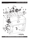
PAGE 10 — PS7060 SERIES MULTIQUIP SAW — PARTS MANUAL — REV. #8 (07/26/10)
INCH
MM
0
25
50
0
1
2
3
75
100
125
150
175
200
230
255
280
305
330
355
380
15
9
10
11
12
13
14
4
5
6
7
8
WATER PUMP
WATER PUMP
OFF
ON
ON
WATER
OFF
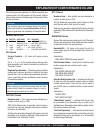
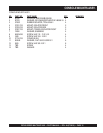
BRAKES:
This saw is equipped with parking brakes.
This saw is equipped with parking brakes.
Brakes are applied automatically when engine
Brakes are applied automatically when engine
is off and dis-engaged when engine is running.
is off and dis-engaged when engine is running.
BEFORE
STARTING:
WATER
SUPPLY:
BLADES:
STARTING
ENGINE:
STOPPING
ENGINE:
FWD-
NEUTRAL-
NEUTRAL-
REV
CONTROL:
RAISE-
RAISE-
LOWER
FUNCTION:
Check all fluid levels. Secure blade firmly to
Check all fluid levels. Secure blade firmly to
bladeshaft. Make sure all protective guards
bladeshaft. Make sure all protective guards
are in place and properly mounted. Wear eye,
are in place and properly mounted. Wear eye,
ear protection and protective clothing.
ear protection and protective clothing.
Connect water supply to water inlet. Move
Connect water supply to water inlet. Move
water ON/OFF CONTROL to ON position.
water ON/OFF CONTROL to ON position.
Adjust WATER FLOW CONTROL lever to
Adjust WATER FLOW CONTROL lever to
desired position. Drain watering system in
desired position. Drain watering system in
cold weather to prevent damage due to
cold weather to prevent damage due to
freezing.
freezing.
Always follow blade manufacturer's
Always follow blade manufacturer's
recommendations for blade selection,
recommendations for blade selection,
speed and application.
speed and application.
NEVER exceed blade manufacturer's
NEVER exceed blade manufacturer's
maximum rated RPM. See operator's manual
maximum rated RPM. See operator's manual
for detailed blade mounting instructions.
for detailed blade mounting instructions.
Set CONTROL HANDLE to NEUTRAL position.
Set CONTROL HANDLE to NEUTRAL position.
Set THROTTLE to IDLE. Turn start switch to
Set THROTTLE to IDLE. Turn start switch to
ON position. Wait for glow plug indicator light
ON position. Wait for glow plug indicator light
to go out. Momentarily turn switch to start
to go out. Momentarily turn switch to start
position; release switch as soon as engine
position; release switch as soon as engine
starts. Allow engine to warm up for several
starts. Allow engine to warm up for several
minutes before increasing engine speed. Use
minutes before increasing engine speed. Use
approved diesel fuel only.
approved diesel fuel only.
Do not stop engine abruptly when hot! Reduce
Do not stop engine abruptly when hot! Reduce
THROTTLE to IDLE and allow engine to run 1
THROTTLE to IDLE and allow engine to run 1
to 2 minutes before turning ignition switch off.
to 2 minutes before turning ignition switch off.
Damage to engine may occur if not allowed to
Damage to engine may occur if not allowed to
cool adequately.
cool adequately.
The panel mounted handle controls
The panel mounted handle controls
FORWARD, NEUTRAL and REVERSE
FORWARD, NEUTRAL and REVERSE
operation. Neutral position stops or holds saw
operation. Neutral position stops or holds saw
in a stationary position. Incremental
in a stationary position. Incremental
movement in the FORWARD or REVERSE
movement in the FORWARD or REVERSE
direction will increase speed proportionate
direction will increase speed proportionate
to amount of movement.
to amount of movement.
RAISE-LOWER function is controlled by the
RAISE-LOWER function is controlled by the
switch mounted at the right side of the
switch mounted at the right side of the
CONTROL HANDLE. Push toggle switch
CONTROL HANDLE. Push toggle switch
lever forward to lower saw. Pull toggle switch
lever forward to lower saw. Pull toggle switch
lever backward to raise saw.
lever backward to raise saw.
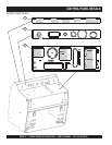
OPERATING INSTRUCTIONS
OPERATING INSTRUCTIONS
FORWARD
NEUTRAL
REVERSE
WARNING
BLADESHAFT ROTATIONDIS -ENGAGEMENT SYSTEM
BLADESHAFT ROTATIONDIS -ENGAGEMENT SYSTEM
Engine must be at idle when engaging or
Engine must be at idle when engaging or
dis-engaging bladeshaft drive.
dis-engaging bladeshaft drive.
To stop bladeshaft rotation:
To stop bladeshaft rotation:
Push rocker switch labeled BLADESHAFT forward.
Push rocker switch labeled BLADESHAFT forward.
Engine will tilt forward, dis-engaging the belt drive.
Engine will tilt forward, dis-engaging the belt drive.
To start bladeshaft rotation:
To start bladeshaft rotation:
Push rocker switch labeled BLADESHAFT backward.
Push rocker switch labeled BLADESHAFT backward.
Engine will tilt back, engaging belt drive.
Engine will tilt back, engaging belt drive.
ENGINE MUST BE SHUT OFF
ENGINE MUST BE SHUT OFF
when removing or installing
when removing or installing
blade or bladeguard or performing any type of service
blade or bladeguard or performing any type of service
to bladeshaft or any other component on machine!
to bladeshaft or any other component on machine!
NEVER
attempt to remove or install blade or bladeguard
attempt to remove or install blade or bladeguard
with engine running by dis-engaging the belt drive!
with engine running by dis-engaging the belt drive!
NEVER
attempt to service any component with the
attempt to service any component with the
engine running!
engine running!
NEVER
leave saw unattended while engine is running!
leave saw unattended while engine is running!
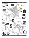
RAISE/LOWER
SWITCH
FWD-NEUTRAL-REV
CONTROL
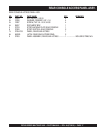
NEVER EXCEED BLADE MANUFACTURER'S RECOMMENDED RPM'S
NEVER EXCEED BLADE MANUFACTURER'S RECOMMENDED RPM'S
ADJUST WATER FLOW VALVE
ADJUST WATER FLOW VALVE
FOR DESIRED WATER FLOW
FOR DESIRED WATER FLOW
WATER
FLOW
CONTROL
TO ADJUST CUT DEPTH INDICATOR:
TO ADJUST CUT DEPTH INDICATOR:
LOWER SAW UNTIL BLADE CONTACTS
LOWER SAW UNTIL BLADE CONTACTS
SURFACE, ADJUST DIAL TO ZERO.
SURFACE, ADJUST DIAL TO ZERO.
DEPTH
INDICATOR
To Control Depth of Cut with Saw
To Control Depth of Cut with Saw
Running and Blade Mounted:
Running and Blade Mounted:
Step 1:
Step 1:
Raise saw above desired cutting depth.
Raise saw above desired cutting depth.
Step 2:
Step 2:
Turn depth control knob counterclockwise
Turn depth control knob counterclockwise
until saw cannot be lowered by pushing raise/lower
until saw cannot be lowered by pushing raise/lower
switch forward.
switch forward.
Step 3:
Step 3:
Hold raise/lower switch in the lowering
Hold raise/lower switch in the lowering
position and rotate the depth control knob clockwise
position and rotate the depth control knob clockwise
until desired cutting depth is achieved. The saw will
until desired cutting depth is achieved. The saw will
repeat to the same depth until re-adjusted.
repeat to the same depth until re-adjusted.
To Re-adjust for Full Cutting Depth:
ToRe-adjust for Full Cutting Depth:
Hold raise/lower switch in the lowering position and
Hold raise/lower switch in the lowering position and
rotate the depth control knob clockwise until saw is
rotate the depth control knob clockwise until saw is
fully lowered. Rotate depth control knob clockwise
fully lowered. Rotate depth control knob clockwise
additional 1 turn.
additional 1 turn.
DEPTH STOP CONTROL
DEPTH STOP CONTROL
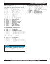
MAINTENANCE INSTRUCTIONS
ENGINE
Air filter: Replace outer element when the SYSTEMS
air filter restriction light comes on.STATUS
Replace inner element every fourth outer element.
Oil: Check oil level daily, do not overfill.
Oil type:
See Engine Manual.
Oil Service: Change oil and filter every 125 hours
of operation.
Fuel Filter:
Change fuel filter every 250 hours of operation.
HYDRAULIC SYSTEM
Oil Level: Check reservoir daily. Fill reservoir to
line marked
FULL COLD.
Oil type:
15W-40 premium grade engine oil.
Oil Service:
Change oil and filter every 500 hours of
operation or annually, whichever occurs first.
Reservoir Reservoir is located inside console. Remove
Location:
rear panel for access.
Wheel drive propulsion system, lift pump,
and oil bath bladeshaft share common
hydraulic oil reservoir, thus are maintained
as a single system.
LUBRICATION
Service:
Grease every 125 hrs. of operation.
Type:
Note:
Use premium grade waterproof
EP (extreme pressure) grease.
Locations:
Front axle pivot bearings (2), lift
cylinder pins (2), engine tilt cylinder
pin (1).
DRIVE BELTS
Belt Tension:
Bladeshaft drive belt tension is applied hydraulically when
bladeshaft drive is engaged.
To Adjust
Perform following procedure with saw fully lowered.
Drive Belt
Loosen jam nut on belt tension limiting bolt. Turn belt tension limiting bolt
counterclockwise to create ½” minimum distance between end of bolt and frame.
Start engine and engage belt drive;increase engine speed to full throttle position for
15 seconds minimum.Slow engine speed to idle and shut engine off.Turn belt
tension limiting bolt clockwise until bolt lightly contacts frame.Tighten locknut.
Tension:
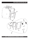
ENGINE WILL NOT CRANK
OR START WHEN E-STOP
BUTTON IS DEPRESSED
TACHOMETER
SYSTEMS STATUS
BLADE SPEED
ENGINE PRE-HEAT
GLOW PLUG
ON
ENGINE
PRE-HEAT
START
OFF
IGNITION SWITCH
ENGAGE
OFF
OFF
BLADESHAFT
DIS-ENGAGE
LIGHTS
ON
AUXILIARY
ON
THROTTLE
TO INCREASE ENGINE SPEED:
TURN KNOB COUNTERCLOCKWISE.
TO REDUCE ENGINE SPEED:
TURN KNOB CLOCKWISE.
FOR QUICK THROTTLE ACTION: DEPRESS RED BUTTON AND
PUSH OR PULL KNOB.
1
2
3
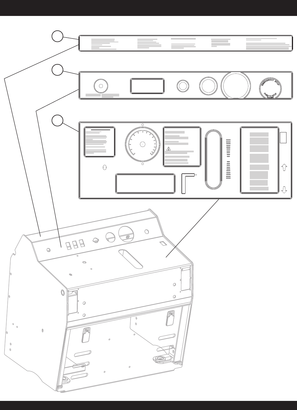
CONTROL PANEL DECALS
CONTROL PANEL DECALS