


PAGE 28 — TP24 TILE SAW • OPERATION AND PARTS MANUAL — REV. #2 (04/12/12)
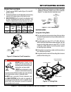
REALIGNMENT
Method 1
This procedure deals with the most common source of
misalignment that occurs when the guide rails are not
parallel with the blade.
1. Set the cutting depth such that the blade passes
through the table, not over.
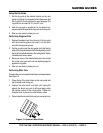
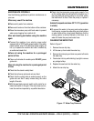
2. Place a straight edge (i.e. carpenter’s square) on the
cutting table as shown in Figure 20.
3. Loosen the left and right guide rails by loosening the
fasteners found at the ends of the rail. The left rail
should be slightly loose, so there is not too much play
during adjustments, but the right rail should move freely.
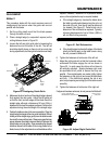
Figure 20. Realigning Guide Rails
4. Make sure the short portion of the straight edge is placed
flush against the ruler guide. Adjust the left guide rail
so that the front and rear edges of the blade touch the
straight edge, although a tolerance of 0.1mm (.004 in.)
between the front and rear edges is allowed. Perform this
adjustment along the entire length of the straight edge.
5. Position the table as close to the user as possible. Place the
straight edge flush against the ruler guide and blade. Without
holding onto the straight edge, gently move the table towards
the rear of the saw and then back. Observe any gaps that may
appear between the straight edge and blade or between the
straight edge and ruler guide. A gap exceeding the allowed
tolerance means that the table is not moving parallel to the
blade; hence, further adjustments as outlined below will be
FASTENER
RULER
GUIDE
STRAIGHT
EDGE
RIGHT
GUIDE
RAIL
LEFT
GUIDE
RAIL
FRONT
OF THE
SAW
required. However, if scenario A or B (described below)
occurs, other adjustments may be required instead.
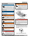
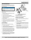
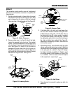
a. If the straight edge only touches the blade when
the table is positioned midway along the rail or at
the ends of the rail, then the rail may be deformed
(i.e. bowed). See Figure 21. Perform test cuts to
determine if the rail should be replaced. Typically,
a bowing displacement of up to 0.2mm (.008 in.)
will not affect cutting accuracy.
Figure 21. Rail Deformation
b. If the straight edge touches both edges of the blade
intially, but shifts apart as the table travels along
the rail, proceed to Method 2.
6. Tighten the fasteners at both ends of the left rail.
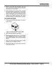
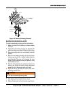
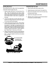
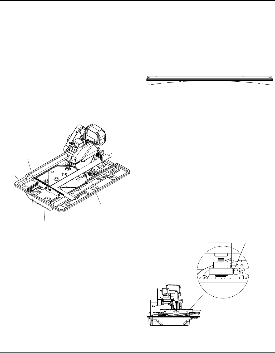
7. Adjust the right guide rail so that the horizontal rollers
underneath the table engage the rail as shown in
Figure 22. In most cases the rollers will not have to
be vertically adjusted. Spacing between rails must
be equidistant at all points to ensure that they are
parallel. Once adjustments are made, lightly tighten
the fasteners on the right rail and move the table back
and forth. If the table binds against the rail at any
point, adjust spacing accordingly until the table moves
smoothly.
8. Tighten the fasteners at both ends of the right rail.
If alignment has been achieved, do not proceed to Method 2.
Figure 22. Adjust Right Guide Rail
LEAVE HAIRLINE GAP
BETWEEN RAIL AND ROLLER
LEAVE A 1/32 IN.
(1MM) GAP
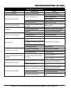
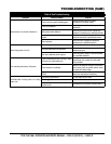
MAINTENANCE