


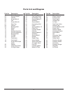
4
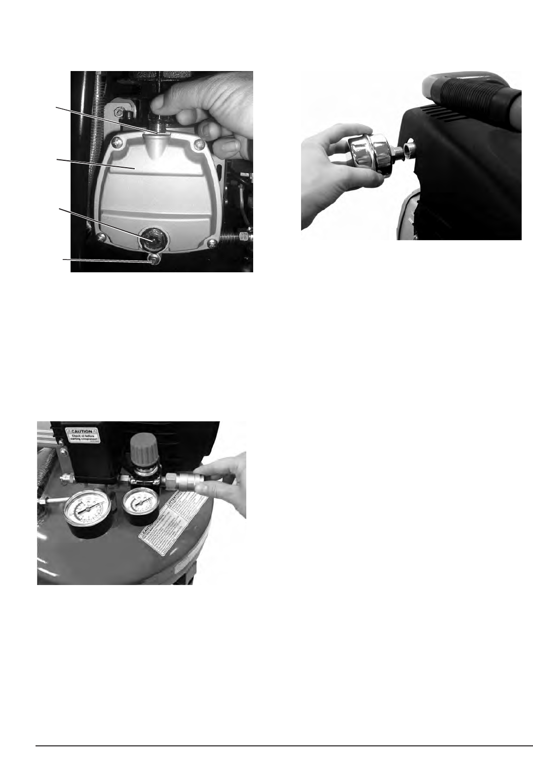
Installing the Air Chuck
Note: The use of a sealant tape is recommended
on the threads of the Air Chuck to prevent air
leakage.
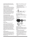
1. Thread the Air Chuck into the Air Regulator by
turning the Air Chuck clockwise.
2. Securely tighten the Air Chuck in place with a
wrench.
Note: DO NOT over tighten Air Chuck.
(See Figure 3)
Installing the Air Filter
The metal Air Filter is installed into the threaded
port of the cylinder head.
1. Thread the Air Filter into the Cylinder Head by
turning the Air Filter clockwise.
2. Securely tighten the Air Filter in place with a
wrench.
(See Figure 4)
Note: DO NOT over tighten Air Filter.
OPERATION
BEFORE OPERATING YOUR NEW AIR
COMPRESSOR please check the following points
carefully:
1 Check that all nuts and bolts are secure.
2. Make sure oil has been properly added to
compressor. (See Installing Oil and Oil Breather
Cap section.)
Initial Start-Up Procedure
1. Open the Air Tank Drain Valve to permit air to
escape, preventing air pressure buildup in the
air tank.
2. Run the compressor for a minimum of 20
minutes in this “no-load” position to lubricate the
piston and bearings.
3.
Close
Air Tank Drain Valve. Your compressor is
ready for use.
Depending on the CFM draw of the tools being
operated, your new Air Compressor can be used for
operating paint sprayers, air tools, grease guns,
airbrushes, caulking guns, abrasive blasters, tire &
plastic toy inflation, spraying weed killer and
insecticides, etc. Proper adjustment of the Air
Pressure Regulator is necessary for all of these
operations. Refer to the air pressure specifications
provided with the tool you are using.
General Overview
To compress air, the piston moves up and down in
the cylinder
. On the down stroke air is drawn in
through the valve inlet.
The discharge valve remains
closed. On the upstroke of the piston air is
compressed.
The inlet valve closes and air is forced
out through the discharge valve, through the check
valve, and into the air tank. W
orking air is not
available until the compressor has raised the tank
Figure 3. Installing the
Air Chuck
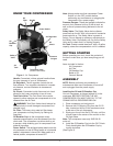
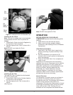
Figure 2. Installing the Oil & Oil Breather Cap
Figure 4. Installing the Air Filter
Oil
Fill
Crank-
case
Oil
Sight
Glass
Drain
Plug