


8
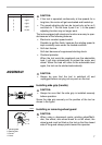
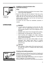
Loosen the lever on the wheel guard. Mount the wheel guard
with the protrusion on the wheel guard band aligned with the
notch on the bearing box. Then rotate the wheel guard
around 180 degrees. Tighten the lever to fasten the wheel
guard. If the lever is too tight or too loosen to fasten the
wheel guard, loosen or tighten the screw to adjust the tight-
ening of the wheel guard band.
To remove wheel guard, follow the installation procedure in
reverse.
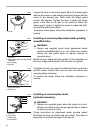
Installing or removing depressed center grinding
wheel/Multi-disc
WARNING:
• Always use supplied guard when depressed center
grinding wheel/Multi-disc is on tool. Wheel can shatter
during use and guard helps to reduce chances of
personal injury.
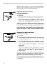
Mount the inner flange onto the spindle. Fit the wheel/disc on
the inner flange and screw the lock nut onto the spindle.
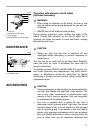
To tighten the lock nut, press the shaft lock firmly so that the
spindle cannot revolve, then use the lock nut wrench and
securely tighten clockwise.
To remove the wheel, follow the installation procedure in
reverse.
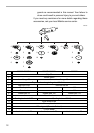
Installing or removing flex wheel
(optional accessory)
WARNING:
• Always use supplied guard when flex wheel is on tool.
Wheel can shatter during use and guard helps to reduce
chances of personal injury.
Follow instructions for depressed center grinding wheel/
Multi-disc but also use plastic pad over wheel. See order of
assembly on accessories page in this manual.
1. Screw
002981
1
1. Lock nut
2. Depressed center grinding wheel/
Multi-disc
3. Inner flange
4. Spindle
002982
1
2
3
4
1. Lock nut wrench
2. Shaft lock
1
2
001084
1. Lock nut
2. Flex wheel
3. Plastic pad
4. Inner flange
1
4
3
2
001096