


2
www.okinternational.com
7000-2250 Rev1
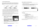
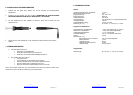
2. INITIAL SETUP
The PS-900 Soldering System consists of a Power Supply, Workstand with Cradle and
Sponge, and a Soldering Handle. The soldering handle also houses a replaceable Coil
Assembly and replaceable heater tip. Both of these consumables are available from your
authorized OK International distributor as needed. The power supply features a Power
Switch, green “Power On” indicator light, power cord, and a connecting port for the solder
handle cord.
1. Mount the power supply in a convenient location in your workspace, such as on the
workbench.
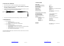
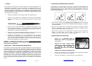
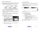
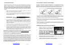
2. Insert a heater tip onto the Coil Assembly and simply push the Heater Tip all the way
until it seats. You should feel a slight “click” as it locks into place.
Insert Tip onto Coil Assembly
3. With the power “Off”, attach the solder handle cord to the power supply by inserting
the cord connector into the power supply connecting port. To align the 3 pins, position
the flat side of the cable connector toward the 9 o'clock position of the power supply.
4. Wet the sponge with de-ionized water until it is moist but not soaked. Then place it in
the workstand tray.
5. Plug the power cord into a grounded wall socket of the appropriately rated input line
voltage. To turn the unit on, push the switch (located on the front of the power supply)
until it latches. The green indicator light should light up. If it does not, see the
“Troubleshooting Guide” in this manual.
CAUTION: To provide continued protection against the risk of electric shock, connect
only to properly grounded
outlets.
3. SMARTHEAT
®
: NO CALIBRATION REQUIRED
The PS-900 System is comprised of an induction coil assembly and a heater tip. Each heater tip
is equipped with a self-regulating heater which ‘senses’ its own temperature and tightly
maintains its pre-set idle temperature for the life of the heater-tip; all controlled by OK
International’s proprietary SmartHeat
®
technology. The tip temperature is determined by the
inherent metallurgical properties of the heater; no external adjustment or equipment is required.
The power delivered to the tip automatically varies in direct response to the thermal load. This
eliminates spikes and transients associated with electrically switched elements found in
conventional soldering irons. Please feel free to contact your OK International representative
with any questions.
3
www.okinternational.com
7000-2250 Rev1
4. SELECTING HEATER TIPS
OK International’s Heater Tips come in a wide variety of tip geometries and temperature ranges
(contact your local OK International Representative or visit our website for more information).
These tip geometries cover a broad range of tasks from delicate precision work to heavy ground
plane soldering.
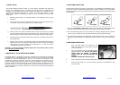
1. Pick a tip that maximizes contact area between the tip and solder joint. Maximizing contact
area gives the most efficient heat transfer, producing high quality solder joints quickly.
2. Pick a tip that allows good access to the solder joint. Shorter tip lengths allow more precise
control. Longer or angled tips may be needed for soldering densely populated boards.
3. Pick the lowest temperature tip cartridge that will accomplish the task. This minimizes the
potential for thermal damage. The temperature series is marked on the shaft of the Heater
Tip.
5. REPLACING HEATER TIPS
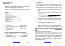
1. Push the Power Switch “Off.” Removal of the
Heater Tip with the power On will result in damage
to the coil assembly.
2. Pull out the heater tip using the supplied AC-CP2
Cartridge Removal Pad. DO NOT USE METAL
TOOLS (SUCH AS PLIERS) TO REMOVE
HEATER TIPS, AS THIS CAN DAMAGE THE
HEATER.
CAUTION: THE HEATER TIP MAY BE HOT!
3. Push a new heater tip into the solder handle with the supplied AC-CP2 Cartridge Pad.
4. Push the Power Switch “On.” The new heater tip will heat up to temperature in less
than 20 seconds.
Too Li
g
ht
Correct
Too Heav
y