3
CY7/670-LR
The gold-coated copper LR adapter is designed
for insertion into a 1/8-inch diameter tube. A thin
layer of CYAG grease should be applied to the
copper adapter before insertion. This eases
installation at room temperature and enhances the
thermal contact.
CY7/670-CU/DI/CY
The gold-coated copper CU, DI and CY adapters
serve as both a sensor and a thermal anchor
assembly. These adapters are designed to be
mounted to a flat surface using a 4-40 brass
screw. Avoid over-tightening the screw; use only
enough force to firmly hold the sensor in place.
Brass is recommended for the screw as the
differential thermal contraction between the
adapter and the screw will cause the mounting
assembly to tighten as opposed to loosen when
the system is cooled. A thin layer of CYAG grease
should be used to enhance the thermal contact
between the adapter and the mounting surface.
The CU adapter has four color-coded leads: red
(I–), green (V–), clear (V+), and blue (I+). The CY
adapter has two color-coded leads: yellow (+) and
green (–). The green lead on the DI adapter is the
cathode.
CY7/670-ET/MT
Both adapters are gold-plated copper hex head
bolts with the SD package mounted in a slot on
the adapter head. The ET adapter screws into a ¼
inch deep, 6-32 threaded hole while the MT
adapter screws into a 6 mm deep, 3 × 0.5 mm
threaded hole. Before assembly, the threads
should be lightly greased with CYAG grease. Do
not over-tighten, since the threads are copper and
can be easily sheared. Finger-tight should be
sufficient.
CY7/670-BO
The BO adapter should be mounted in the same
manner as the CU. The BO adapter contains its
own thermal anchor and is an epoxy-free
assembly.
CY7/670-CO
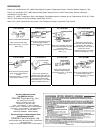
The CO adapter is used to attach the CY7/670-SD
package to a flat surface. The adapter is a spring-
loaded clamp designed to maintain pressure on
the SD package as the temperature is varied.
1. Remove the hold down cap that holds the
three-piece CO assembly together. The CO
assembly should appear as shown in the
accompanying drawings.
2. Bolt the assembly into a 4-40 threaded hole.
The stop on the brass screw should rest
against the mounting surface and it also
prevents overcompressing the spring.
3. Lift the edge of the clip using a small pair of
pliers or screwdriver.
4. Slide the SD package into place underneath
the clip and gently lower the clip onto the lid of
the SD package. Note that a slot is cut
underneath the clip to accept the SD package.
Refer to the drawing for details.
If the device is to be used only below 325 K, a
layer of CYAG grease should be used between
the SD package and mounting surface to enhance
the thermal contact.
Sensor Operation
Temperature controllers and thermometer
instrumentation offered by Omega Engineering,
Inc. are designed to be directly compatible with the
CY7/670 series sensor to give optimum
performance and accuracy together with direct
temperature readouts. Simply follow the
instructions provided with the instrument
concerning sensor connection and instrument
operation. If a user-supplied current source,
voltmeter, or other instrumentation is going to be
used with the CY7/670 series sensor, special
attention should be given to the following details.
The CY7/670 series sensors are designed to
operate at a constant current of 10 µA while the
voltage variation with temperature measurement
depends directly on the specifications of the
current source and the voltmeter. A current source
operating at the level of +0.01 µA (±0.01 K) is
probably suitable for most applications. The
voltmeter resolution required can be estimated
from the sensitivity (dV/dT) of the CY7/670 sensor:
Temperature Sensitivity
(K) (mV/K)
305 2.4
77 1.9
4.2 33
Multiplying the above sensitivity by the desired
temperature resolution in K will give the required
voltage resolution in mV.
The static impedance of the CY7/670 series
sensor operating at 10 µA current is on the order
of 100,000 ohms. Therefore, the input impedance
of the voltmeter must be significantly larger than
this to avoid measurement errors. Voltmeters with
input impedances of greater than 109 or 1010
ohms should be used.
Good quality instrumentation must be used and all
instrumentation and wiring should be properly
grounded and shielded. Temperature
measurement errors will result if there is excessive
AC noise or ripple in the circuitry. Further details
can be found in the article by Krause and Dodrill
given in the references.
Note: All materials mentioned above that are used
in sensor installation are available from OMEGA
Engineering, Inc.


