


pg. 9 of 29
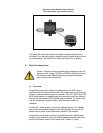
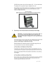
Units are supplied with an integral 4 pin connector. Connections to the unit
are made using a mating cable assembly or power adapter package as
detailed in the following sections. A connector pin and wire color cross
reference may also be found in Appendix F (Page 18) of this manual.
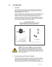
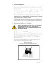
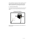
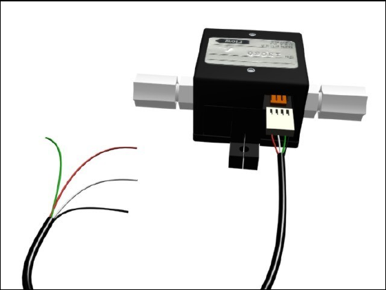
b) Connecting a Cable Assembly
The connector on the end of the cable assembly should be pushed into the
mating socket on the sensor taking care to ensure that it is the correct
way up.
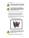
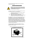
Connecting the Cable Assembly
(FLR 1000 shown, other models similar)
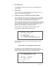
Electrical connections to the cable assembly are made as detailed in the
following sections.