


Max scale should not be more than 50% FS because of noise related
issues.
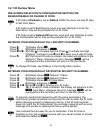
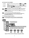
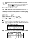
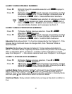
Press
d
27) Display flashes
STRD
stored message momentarily and then
advances to
ALR1
only, if a change was made, otherwise
advances to
ALR1
Alarm 1 Menu.
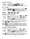
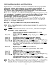
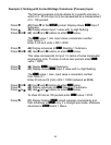
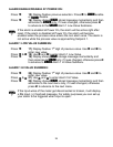
Example 2: Scaling without Known Loads.
If
DSBL
Disabled Load Submenu was selected, instrument is ready for
scaling Without Known Loads method.
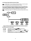
To scale without known inputs, calculate inputs based on transducer specifications
and manually enter them on the via front panel push-buttons. The following example
assumes load cells with this specification:
Maximum Load: 100.0 lb
Output: 3.0 mV/V
Sensor Excitation 10 V
Maximum Sensor Output = 3.0 (mV/V) x 10 (V) = 30 mV
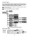
1. Determine the correct values for Inputs
(
IN!1 and IN!2
)
.
Calculate IN!1 and IN!2 using the following equation:
IN
= (Sensor Output) x (Converison Number) x (Multiplier)
Conversion number is a coefficient of conversion between input values
and real full display range (10000 counts). See Table 3.1 below for proper
conversion number.
Table 3.2 Conversion Table
INPUT RANGE CONVERSION NUMBER
0 ~ 100 mV 10000 / (100 x 1) = 100 cts/mV
0 ~ 1 V 10000 / (1000 x 1) = 10 cts/mV
0 ~ 10 V 10000 / (1000 x 10) = 1 cts/mV
0 ~ 20 mA 10000 / (20 x 1) = 500 cts/mV
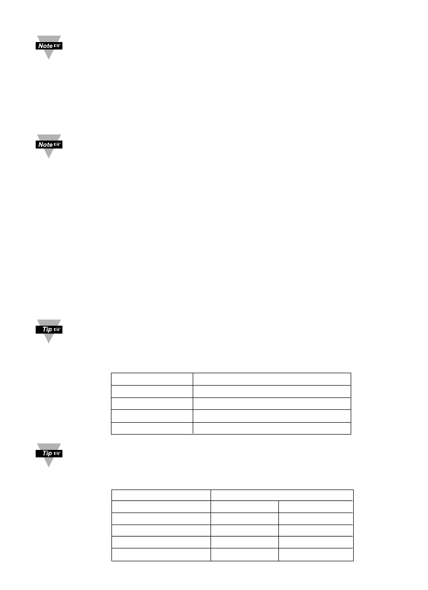
Multiplier determined by the Input Resolution setting
(
RESO
in the
INPT
Menu). See Table 3.2 below for proper multiplier.
Table 3.3 Input Resolution Multiplier
INPUT RANGE RESOLUTION
LOW HIGH
0 ~ 100 mV 1.0 10.0
0 ~ 1 V 1.0 10.0
0 ~ 10 V 1.0 10.0
0 ~ 20 mA 1.0 10.0
23