


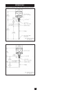
SPECIFICATIONS
SAFETY
Power: 115VAC (
±
15%); 2.5VA; 50/60Hz / 230VAC (
±
15%); 2.5VA; 50/60Hz
Altitude: 6562 ft (2000 m) max
Installation Category: II
Pollution Degree: 4 (Reduced to 2 by enclosure) Suitable for indoor/outdoor use
Ambient Op Temp: -40˚ F (-40˚ C) to +150˚ F (+65˚ C)
*
Internal Bin Temp: To +176˚ F (+80˚ C) w/alum. mount (<104˚ F (40˚ C) ambient)
To +400˚ F (+204˚ C) w/SS mount (<122˚ F (50˚ C) ambient)
Output Relay: SPDT, 5A @ 250VAC, 30VDC maximum
External Indicators: Red and green LEDs indicating power and operating mode
Sensitivity: Multi-turn potentiometer adjustment 0.5pf to 150 pf
Stability:
±0.015pf per degree F (±0.027pf per degree C) @ 0.5pf setting
Time Delay: 0.25 to 15 sec delay-to-activate, adjustable
0.25 sec delay-to-deactivate, fixed
Fail-Safe: Switch selectable - HI/LO
Build-up Immunity: Protected via driven shield to 150 ohm load
Enclosure: Cast alum screw-on cover, beige polyester pwdr coat, NEMA 4, IP66
Conduit Connection: Two (2) 3/4” NPT connections
**Approvals: CSA
US
CSA
C
Ordinary Locations, CE Mark(Ordinary location only)
Standard/Food Grade Probe
Mounting: 1-1/4” NPT alum or combo 3/4” NPT 316SS and 1-1/4” NPT alum
Probe Material: 3/8in(9.5mm) dia. 316SS probe & guard, PPS insulators
Probe Length: 16in(406mm) from alum mounting
Temp (Probe Only): PPS+450˚ F (+232˚ C) max;
Pressure:
50 psi(3.5 bar) max (alum connection);150 psi(10 bar) max (3/4” NPT SS)
Stub Probe
Mounting: 1-1/4” NPT alum, or combo
3/4” NPT 316SS and 1-1/4” NPT alum
Probe Material: 3/8in(9.5mm) dia. 316SS probe & guard, PPS insulators
Probe Length: Cut to customer specification; application dependent
Temp (Probe Only): PPS +450˚ F (+232˚ C) max
Pressure: 50 psi(3.5 bar) max (aluminum); 150 psi(10 bar) max (3/4 NPT SS)
*Influenced by mounting, material thermal conductivity and ambient temperature.
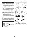
General Safety
CAUTION: It is essential that all instructions in this manual be followed to
ensure proper operation of the equipment and safety of operating person
-
nel. Use of equipment not specified herein, may impair protection provid
-
ed by equipment. The use of this symbol is used throughout manual to
highlight important safety issues. Please pay particular attention to these
items.
Electrical Shock Caution
Certain LV800 models are powered with HIGH VOLTAGE. No operator
serviceable parts are inside. All servicing is to be performed by qualified
personnel. Each MK-2e is provided with a "protective conductor terminal"
which shall be terminated to earth ground potential (See Electrical
Installation). This product's design complies with EN61010-1 installation
category II and pollution degree 2.
Electromagnetic Compatibility (EMC)
The LV800 was tested and found to comply with the standards listed
below. The LV800 should not be used in residential or commercial envi-
ronments. Compliance to EMC standards was demonstrated by means of
a test setup using the following installation methods.
1) LV800 enclosure was connected to earth ground (protective
earth).
2) No specific wiring convention was used to supply power or
to retrieve output signal from the LV800.
EMC Emissions:
Meets EN 61326-1 Electrical Equipment for Control Use, EMC
EN 55011 Radiated and conducted emissions
(Class A- industrial)
EN 61000-3 Fluctuations/Flicker
Meets FCC Part 15B: RF Devices, Unintentional Radiators
CISPR 11 Radiated and conducted emissions
(Class A- industrial)
EMC Immunity:
Meets EN 61326-1 Electrical Equipment for Control Use,
EMC
IEC 1000-4-2 Electrostatic discharge (industrial)
IEC 1000-4-3 RF radiated EM fields (industrial)
IEC 1000-4-4 Electrical fast transients (industrial)
IEC 1000-4-5 Electrical surges (industrial)
IEC 1000-4-6 RF conducted EM energy (industrial)
IEC 1000-4-8 Power frequency magnetic fields
(industrial)
IEC 1000-4-11 Source voltage deviation
9