


3
The DRA-DCC-8 is powered by a DC power supply at a range of 15-32Vdc. In order
to determine the minimum supply voltage, use the following equation:
Vmin = 8 + Rload(
Ω) * 0.02
where:
Vmin is the minimum required supply voltage.
Rload(
Ω) is the maximum output load including the leads resistance.
Note: If Vmin turns to be less than 15V, the minimum required voltage
should be 15 Vdc.
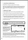
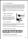
5. MODES OF OPERATION
The DRA-DCC-8 unit can be operated in several modes, determined by an internal
array of 8 DIP switches as follows:
4-20 or 0-20mA output current mode
Parallel control mode
Serial control mode
Self test mode
5.1 0-20 OR 4-20mA OUTPUT CURRENT MODE
Two current output spans are available: 4-20mA or 0-20mA selected by SW6.
The DRA-DCC-8 receives 12 bits of data which determine the output current value.
A channel data value of 4095 (FFF) is always interpreted as a 20mA output current.
A channel data value of 0 (000) will produce a 0mA output current when SW6
is OFF, or 4mA when ON.
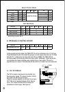
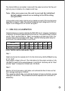
5.2 SWITCH SETTINGS
Parallel Control Mode
S1 S2 S3 S4 S5 S6 S7
0-20mA
4-20mA
OFF OFF OFF OFF
XXX
OFF OFF ON OFF
XXX
MODE
4. SUPPLY VOLTAGE