


Installation
CAUTION:
1. INCORRECT ELECTRICAL CONNECTIONS CAN, IN CERTAIN CIRCUMSTANCES, DESTROY THE
ELECTRONIC
OUTPUT CIRCUIT.
2. BEFORE APPLYING ELECTRICAL POWER, MAKE SURE THE SUPPLY VOLTAGE IS TO THE CORRECT
RATING
.
3. THIS A VERY SENSITIVE SENSOR, ONLY APPLY PRESSURE WITHIN THE PRESSURE RANGE.
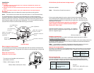
Mounting
Two M5 threaded holes in the base of the sensor provide mounting points.
Note: The screws must not enter the holes more than 0.4" into the sensor body.
The installed position of the sensor should be away from sudden temperature
variations, shocks and vibrations and should not be close to strong electromagnetic
fields (transformers, motors etc.). The sensor can be mounted in any position, but
mounting at an angle may require zero adjustment. For very low pressure sensors
(less than 2.0 inH
2
O) the recommended mounting is horizontal.
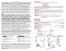
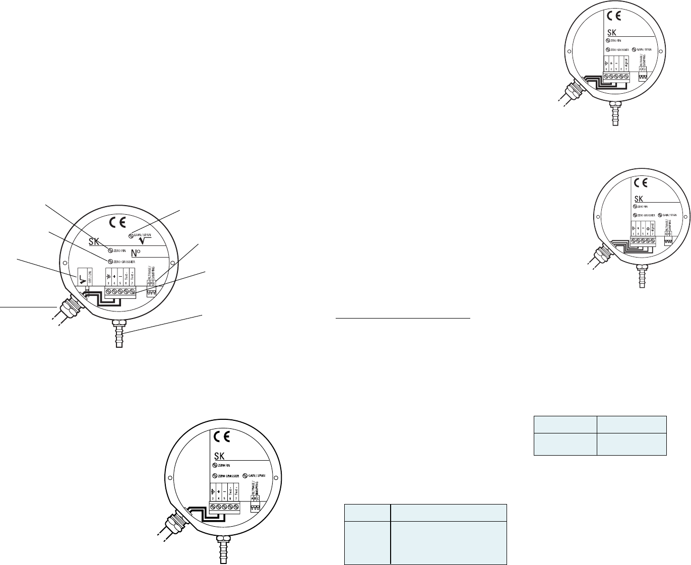
zero adjustment
(fine)
zero adjustment
(coarse)
span adjustment
filter time response
selector switch
terminal connector
block
square root output
selection switch
(optional)
gland nut
(cable entry)
pressure connector
Electromagnetic Interference
To avoid electrical interference, use shielded cable with the shield connected to the
earth ground at both ends. The ground of the sensor can be the casing or the ground
terminal screw.
Electrical connections
PX548 Series (current output)
The maximum allowable load resistance is
calculated to formula:
R Max = 0.05 (V supply - 10) kW
Where: R Max in kW and V in Volts
PX548 Series (Unidirectional voltage output)
Minimum load 2 k
W
Note: Connections 5 and 6 are common
If the output cable passes through an area of electrical disturbance, use a
recommended load impedance of between 2 kW and 10 kW . Connect the load
resistance between the wires corresponding to signal and - terminal at a point
furthest from the sensor.
PX548 Series bidirectional operation using bipolar
power supply (±12 Vdc) with bidirectional output
(0±5 Vdc or 0±2.5 Vdc)
Minimum load 1 k
W
Pressure connections
The high pressure connector is marked
+
and the low pressure connector is marked
–.
Purging or de-gasing the sensor
Two 5 mm hexagonal socket bleed screws are located on the outer casing and can be
loosened to bleed the two pressure connectors. Make sure that these screws are
tightened after this operation.
Note: It is possible to changeover the bleed screws and pressure connectors
enabling easier access or permitting installation in a difficult position.
Square root output option
This option only applies to the LPX 5000 sensor with 4 to 20 mA two wire connection
and the square root electronics assembly fitted. A switch next to the terminal block
selects the output mode.
Switch Output mode
OFF Linear
ON Square root
Internal detail
Filter response time
The filter response time of the sensor, additional to the built-in response time of 10
milliseconds (approximately), can be set using the three switches next to the
terminal connector. Using combinations of the switches can set different times.
Note: A hollow point is visible when a switch is in the 'on' position.
Example:
Switch A+B = 600 milliseconds
Switch Filter response time
A 200 milliseconds
B 400 milliseconds
C 1 second
Connect the power supply to + for positive, - for negative,
and 0 for neutral; connect the output to signal for positive
and 0 for negative signal.