


Operation
10 900-0114-01-00 Rev A
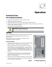
5. If the INVERTER LED (green) is not illuminated, turn on the inverter using the system display or
external switch.
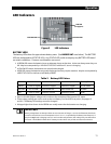
6. Check the STATUS LEDs. Confirm that the INVERTER LED (green) is illuminated.
7. Using a DVM, verify 120 Vac between the AC HOT OUT and AC NEUTRAL OUT terminals. Do not
turn on any AC breakers or disconnects at this time.
8. Perform all programming for stacking, battery charging, AC current, generator starting, and any
other functions. Refer to the Description of Functions section beginning on page 13, the system
displ
ay man
ual, and any other literature as needed.
After programming is completed, perform the following steps:
1. If other inverters are on the system, use a DVM to verify correct voltage from AC HOT OUT on one
inverter to the next. Series-stacked inverters should collectively read 240 Vac. Parallel-stacked
inverters should collectively read 0 Vac (although individually they should still read 120 Vac).
Three-phase inverters should collectively read 208 Vac.
2. Close the AC output breakers or disconnects. If AC Bypass breakers are present, place them in the
normal (non-Bypass) position. Do not connect an AC input source or close any AC input breakers.
3. Use a DVM to verify correct voltage at the AC load panel.
4. Connect a small AC load and test for proper functionality.
5. Close the AC input breakers and connect an AC source.
6. Check the STATUS LEDs. The AC IN LED (yellow) should flash. The INVERTER LED will remain
illuminated for a short time. When the AC IN LED stays illuminated, the INVERTER LED should go
dark. This means the inverter is no longer drawing on batteries, but is using the AC source.
7. If the battery charger has been enabled, confirm that it is charging by using the system display.
The inverter will perform a full battery charge when first powered up. This may take several hours.
If restarted after a temporary shutdown, the inverter may skip most or all of the charging cycle.
8. Test any other functions which have been enabled, such as generator start, selling, or
search mode. GFX Series inverters have a minimum one-minute delay before selling will begin.
9. Compare the DVM’s readings with the system display meter readings. If necessary, the system
display’s readings can be calibrated to match the DVM more accurately. AC input voltage, AC
output voltage, and battery voltage can be calibrated.
Powering Down
If steps are inapplicable, they can be omitted. However, it is highly recommended that all applicable
steps be performed in the following order.
To Power Down the System:
1. Turn off all load breakers and AC input breakers.
2. Turn off all renewable energy breakers.
3. Turn each inverter OFF using the system display or external switch.
4. Turn off the main DC breaker for each inverter.
Adding New Devices
When adding new devices to the system, first power down the system according to the preceding
instructions. After adding new devices, perform another functional test, including programming.