


Ref.No.2D Procedure 2A →
→→
→ 2B →
→→
→ 2C →
→→
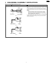
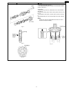
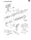
→ 2D Assembly of the Adjusting Screw and the Clutch Handle.
Fig. 12
Fig. 13
1. Hold the driving block with the click spring on top, and align the
smallest projection of adjusting screw with the driving block at 5
o´clock position.
NOTE:
Make sure that the adjusting screw has its own correct direction
for proper assembly. Failure to do so, the clutch handle does
not rotate properly. (See Fig. 12)
2. Turn the adjusting screw into the driving block about 255°rotation
(to 2 o´clock position) for clockwise direction. (See Fig. 13)
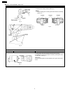
3. Set the clutch handle with position 1 on top. (See Fig. 14)
Fig. 14
Ref.No.2E Procedure 2A →
→→
→ 2B →
→→
→ 2C →
→→
→ 2D →
→→
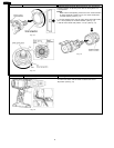
→ 2E Assembly of the Switch.
Fig. 15
1. Press fit the lead wires firmly and set the black lead wire on top.
2. Connect the switch with the white and black lead wire at
55°position. (See Fig. 15).
6
EY6450-U1