


2
WCS-SIF-01
Training & Maintenance Manual
Pneumati
c
Parker Hannifin Corporation
Pneumatic Division
Richland, Michigan
www.parker.com/pneumatics
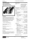
Description & Operation
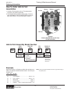
General Description of Spotwelding Units
The spotwelding system is an integrated pneumatic
controlled circuit that is specifically designed to increase
production throughput, while improving weld quality and
reducing decibel noise level.
Each unit consists of 2 independent, 2 position, directional
control valves for retract (pre-stroke) and weld stroke. Each
valve is dual pressure, with single solenoid / spring assist
return or double solenoid available. Also included with each
unit is a proportional / quick dump valve, a feedback sensor
for initiating the welding process, and a flow control for
metering the impact speed of the weld tips.
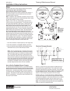
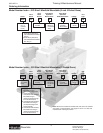
General Operation of
Spotwelding Units – 3 ported guns
Spotwelding systems control both retract (pre-stroke) and
weld stroke motions. When a 3 ported cylinder is used, the
control block functions as follows:
1. The pre-stroke (retract) valve is energized, allowing
the weld cylinder to extend under full line pressure by
actuating the quick exhaust valve and moving to its
predetermined position prior to welding.
2. The quick exhaust valve time is adjusted by the knob
on top of the unit. To start, the white line on the dial
is set at top dead center. Turn knob clockwise to set
quick exhaust valve open time. Continuing to turn knob
clockwise will lengthen time until it reaches a full 360°
rotation, which covers the complete timing range.
3. The weld stroke valve is then energized using a selected
weld schedule pressure. The closure speed of the weld
tips is controlled by the use of an adjustable flow control,
thus creating “low impact”.
4. Immediately following weld tip contact with the sheet
metal, two actions take place.
a. The proportional / quick dump valve that senses
pressure allows the front end of the cylinder to exhaust
(by-passing the flow control), providing weld schedule
pressure instantly.
b. The proportional / quick dump valve also actuates a
feedback sensor to start the weld cycle.
5.
Once the weld cycle is complete, the weld stroke valve
is de-energized, allowing the weld tips to open under
full pressure.
6. The retract (pre-stroke) valve is then de-energized,
allowing the weld cylinder to open completely under
full line pressure.
Note: Dual pressure is provided to the control block. Line
(high) pressure is used for both retract stroke and weld
stroke open. Weld schedule pressure is used for weld stroke
close. Dual pressure provides for weld tips to be closed for
tip dressing using any pressures available, from as low as
5 PSIG to maximum line pressure.
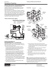
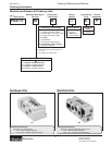
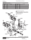
Front View
Back View
Weld Stroke
Valve
Retract
(Pre-Stroke)
Valve
Feedback
Sensor
Flow
Control
Weld Stroke
Valve
Quick
Exhaust
(Air
Operated)
Retract
(Pre-Stroke)
Valve
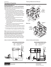
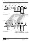
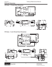
W-
R-
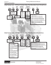
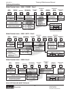
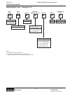
ANSI (3 Ported Cylinder Option)
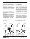
Inductive Sensor / Connection: Turck
Connection Diagram Inductive Sensor
1 Brown +24 VDC Power Supply
3 Blue 0 V Power Supply
4 Black Switch Wire
W+R+
Pw
Pr
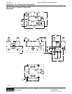
Retract (Pre-Stroke)
Valve
Weld Stroke
Valve
14 4 2 12
14 4 2 12
1
pnp
+
3
-
4