


11 GB/IE/CY
When planing, the parking shoe
16
swings up and
exposes the rear part of the sole
9
.
©
The planing process
½ CAUTION! DANGER OF KICKBACK!
Always switch on the device before placing it
against the workpiece.
˽ Set the required cutting depth.
˽ Switch on the device.
˽ Always place the front part of the sole
9
down first on to the workpiece.
˽ Guide the device with even forward movement
over the surface being planed.
˽ Move the device forward at a slow rate and
ensure that the contact pressure acts evenly on
the sole
9
. Moving forward at too great a
rate results in a poorer surface quality and can
lead to blocking of the planing debris removal
port.
©
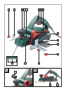
Chamfering edges (see Fig. H)
The V-grooves
10
in the front sole
9
allow the de-
vice to be used for simple chamfering of workpiece
edges.
˽ Use the V-groove most appropriate to your
desired chamfer width.
˽ Place the planer with the V-groove
10
on the
workpiece edge and guide the planer along
the edge.
©
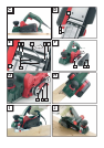
Using the guide fence (see Fig. I)
˽ Attach the guide fence
6
to the device with
the fixing screw
7
.
˽ Release the fixing nut
8
and set the guide at
the desired distance.
˽ Retighten the fixing nut
8
.
˽ Exert some slight sideways pressure when guid-
ing the planer with the guide fence.
©
Using the rebate depth stop
(see Fig. J)
˽ Attach the rebate depth stop
12
to the device
with the fixing screw
11
.
˽ Set the desired rebate depth with the rebate
depth stop
12
.
˽ Make the required number of passes with the
planer until desired rebate depth is achieved.
©
Replacing a planer blade
WARNING!
DANGER OF INJURY!
Before you carry out any work on the device al-
ways pull the mains plug out of the mains socket.
½ CAUTION! The sharp cutting edges of the
planer blade
20
present an injury hazard!
Never touch the cutting edges of the planer
blade
20
.
The planer blade
20
has two cutting edges and it
can be fitted either way around.
˽ Replace the planer blade
20
when both cutting
edges are blunt.
˽ Do not resharpen the planer blades
20
.
©
Removing and installing a
planer blade
20
(see Fig. D)
Reversing or replacing a planer blade
20
IMPORTANT INFORMATION:
Do not release the two Allen keys. They are used to
adjust the height of the blade shaft.
Adjustment is necessary only if you wish to use a
different planer blade type e.g. a profiled blade.
Always replace both blades at the same time to
avoid out of balance forces.
NOTE: If you only release one blade first then you
can use the factory-fitted second blade for orientation
when you fit the new blade.
1. Release the 3 bolts of the cutting element
18
using the supplied open spanner
26
.
˽ Press the removable side guard into the slot in
the housing.
Preparing for use