


15 GB/IE
is beyond the angle of the auxiliary
handle
6
(see Fig. B). Otherwise you
could injure yourself against the grinding or
cutting disc.
˽ Open the clamping lever
8
.
˽ Insert the disc cover guide
7
with the coded
projection
9
in the coded groove
16
.
˽ Turn the disc guard cover
7
into the desired
position (working position). The closed side of
the disc guard cover
7
must always be facing
the operator.
˽ Close the clamping lever
8
to firmly clamp
the disc guard cover
7
in place.
If necessary the clamping force of the connection
can be adjusted by tightening or loosening the
adjuster screw
10
.
Ensure that the disc guard cover
7
sits firmly
on the spindle collar.
©
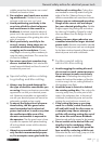
Attaching the auxiliary handle
CAUTION! For safety reasons this
device must always be used with the
auxiliary handle
6
in place. Otherwise
you could become injured.
½
WARNING!
DANGER OF INJURY!
Pull the mains plug out of the mains
socket before you carry out any task
on the device.
˽ Screw the auxiliary handle
6
on the left, right
or on the top of the head of the device.
©
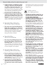
Attaching and replacing
roughing / grinding / cutting discs
Take note of the dimensions of the roughing /
grinding or cutting discs. The circular hole must fit
on to the mounting flange without play. Do not use
a reducer piece or adapter.
½
WARNING!
DANGER OF INJURY!
Pull the mains plug out of the mains
socket before you carry out any task
on the device.
½ Check the condition of the roughing /
grinding or cutting discs. They must be
free of damage, moisture or cracks.
Otherwise they could break up during use and
cause injury.
DANGER OF BURNS! Always wear
protective gloves when changing a
roughing / grinding or cutting disc.
Roughing / grinding and cutting discs become
hot during use. Do not touch them until after
they have cooled down.
½ NOTE: Always ensure the discs are free of dirt
before use.
½ Use only abrasive consumables or tools with
an allowable speed at least as high as the
no-load speed of the device.
½ DANGER OF INJURY! Press the spindle lock
button
11
only after the mounting spindle
14
has reached a standstill.
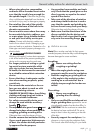
˽ Press the spindle lock button
11
to block the drive.
˽ Release the clamping nut
13
using the spanner
17
(see Fig. C).
˽ Place the roughing / grinding or cutting disc on
to the mounting flange
15
with its labelled side
facing towards the device.
˽ Then replace the clamping nut
13
, with its
raised side facing upwards, on to the mounting
spindle
14
.
˽ Press the spindle lock button
11
to block the drive.
˽ Tighten the clamping nut
13
again with the
spanner
17
.
˽ NOTE: Replace a new disc immediately if it
runs unevenly or vibrates after being exchanged.
˽ After replacing a disc let the device run under
no-load conditions for 30 seconds as a safety
check. Look out for unusual noises or generation
of sparks. Check that all the fastened-on parts
are correctly attached.
˽ Pay attention to see that the arrow showing the
direction of rotation on the roughing / grinding
or cutting discs (including diamond cutting discs)
corresponds with the direction of rotation of the
device (see arrow on the head of the device).
©
Operation
©
Switching on and off
Note: Always switch on the angle grinder before
bringing it into contact with the workpiece material.
Preparing for use / Operation