


1. Configure IP address 40
SmartNode 4520 & 4110 Series User Manual 4 • Getting started with the SmartNode
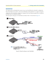
1. Configure IP address
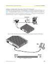
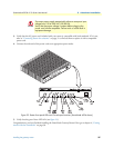
Power connection and default configuration
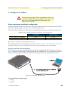
First the SmartNode must be connected to the mains power supply with the power cable. Wait until the 'Run'
LED stops blinking and lights constantly. Now the SmartNode is ready.
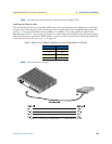
The factory default configuration for the Ethernet interface IP addresses and network masks are listed in table 8.
Both Ethernet interfaces are activated upon power-up.
If these addresses match with those of your network, go to section “2. Connect the SmartNode to the network”
on page 42. Otherwise, refer to the following sections to change the addresses and network masks.
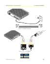
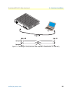
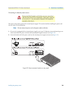
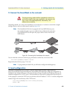
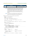
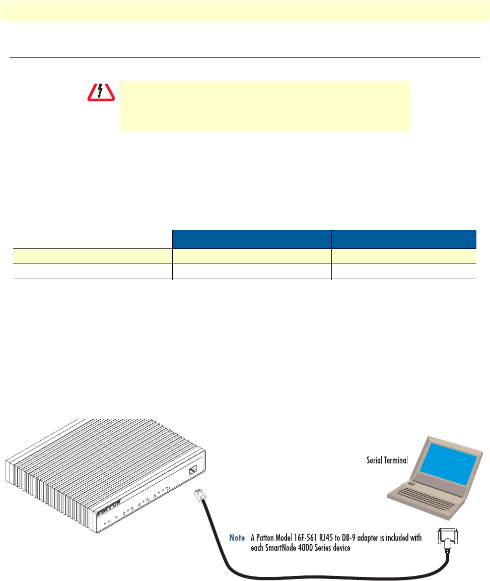
Connect with the serial interface
The Console port is wired as an EIA-561, RS-232 port. Use the included Model 16F-561 adapter and cable (see
figure 25) between the SmartNode’s Console port and a PC or workstation’s RS-232 serial interface. Activate the
terminal emulation program on the PC or workstation that supports the serial interface (e.g. HyperTerm).
Figure 25. Connecting to the terminal
Terminal emulation program settings:
• 9600 bp
• no parity
The Interconnecting cables shall be acceptable for external use
and shall be rated for the proper application with respect to volt
-
age, current, anticipated temperature, flammability, and
mechanical serviceability.
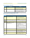
Table 8. Factory default IP address and network mask configuration
IP Address Network Mask
Interface Ethernet 0 (ETH0) DHCP DHCP
Interface Ethernet 1 (ETH1) 192.168.1.1 255.255.255.0
CAUTION
Console
VoIP Gateway Router
ToIP Integrated Access Device
SmartNode 4524
Link
100M
Activity
0/0
0/1
0/2
0/3
E
n
e
t 0
V
o
ic
e
P
o
r
t
s
Power
Run
VoIP Link
Link
100M
Activity
E
n
e
t
1