12 Pelco Manual C573M-D (11/03)
1
2
3
4
8
7
6
5
14 15 16
PGM
MON
120VA
COM1 COM2
UNI
T
WALL BLOCKGROUND
COMPUTER
RECEIVE
COMPUTER
TRANSMIT
PC SIDE
COM1 RJ-45
CONNECTOR
PIN
1PIN 8
RJ-45
CONNECTOR
REVERSED CABLE CONNECTIONS
WALL BLOCK
RJ-45
CONNECTOR
CM9760-MDA
RJ-45
CONNECTOR
PIN 1=TX
PIN 8=RX
REVERSED CABLE
CM9760-MDA
MDA SIDE
12345
678
9
PIN 1=TX
PIN 8=RX
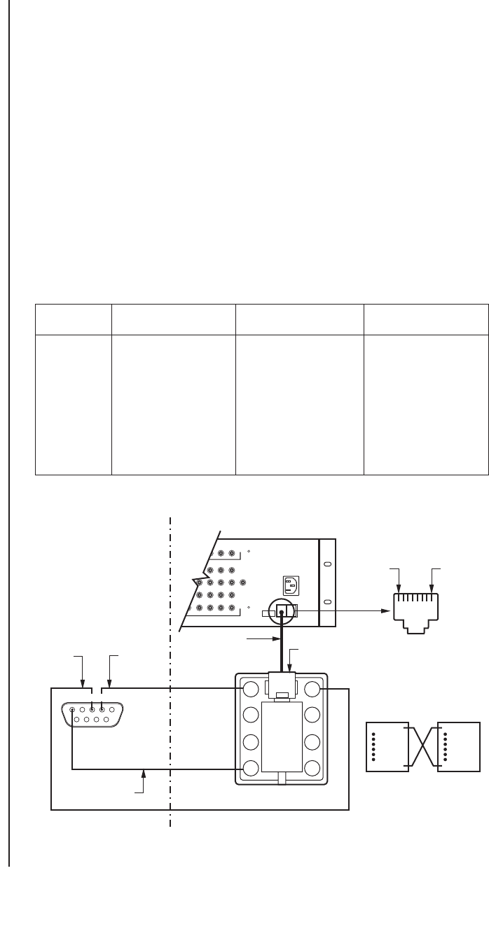
CONNECTING THE MDA TO AN EXTERNAL PC
Perform this step if you are going to program your CM9760-MDA unit using a PC (personal
computer).
Refer to Figure 5 and make a cable to connect the MDA to the PC. The figure shows a
typical nine-pin sub “D” connector for the PC’s COM 1/COM 2 serial port. Computers may
differ regarding connector types and pin-outs. Therefore, always refer to the computer’s
manual to determine proper pin-outs.
If more than one MDA is to be programmed using a PC, note the following:
•A maximum of 16 MDA units can be daisy-chained. To daisy-chain up to 16 MDA units,
connect the RS-422 output of the first MDA unit to the RS-422 input of the second
MDA unit and continue this method until the last MDA unit is connected (refer to Table
D and to Figure 39).
• If more than 16 MDAs are to be connected to a PC, a CM9760-CDU-T must be used.
Refer to Figure 40 for an example of connecting over 16 MDAs to a PC. Note that a
maximum of 64 MDA units can be connected to a PC for programming.
NOTE:
The CM9760-MDA
is configured at the factory
for RS-422 communication.
To communicate via RS-232,
an internal DIP switch must
be changed. Refer to the
Communication Ports Setup
section.
Figure 5. PC Connection to CM9760-MDA
Table D. MDA RJ-45 Connector Pin-Outs
Pin Out RS-232 Function RS-422 Function RS-485 Function
1Transmit Transmit + Transmit +
2 No Connection Transmit - Transmit -
3 No Connection No Connection No Connection
4 Ground Ground Ground
5 Ground Ground Ground
6 No Connection No Connection No Connection
7 No Connection Receive - Receive -
8 Receive Receive + Receive +
NOTE:
The pin numbering
of the wall block shown in
Figure 5 applies to the Pelco
RJ-45 wall block. A wall
block purchased from a
supplier other than Pelco
may have a different pin
numbering scheme.


