


1996 Feb 26 10
Philips Semiconductors Objective specification
Cost effective battery monitor and fast
charge IC for NiCd and NiMH chargers
TEA1104; TEA1104T
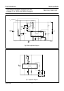
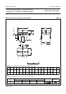
APPLICATION INFORMATION
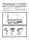
A guideline for the settings of TEA1104 and its external
components selection is given based on an example of a
1 hour charger for a 4 cell NiCd or NiMH battery pack. The
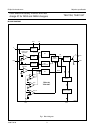
basic application diagram as illustrated in Fig.6 which is
based on the application diagram illustrated in Fig.7 with
some additional components; a 2 LED charge status
indication has been provided.
For charging a battery within one hour the charge current
rating should be as follows:
Required minimum charge current = battery
capacity × 1.2/charge time.
Therefore, for a 1 Ah battery the external charge current
supply has to deliver at least 1.2 A.
TEA1104 settings
The fast charge back-up timer period, time-out, has to be
set in relation to the expected maximum charge time.
Normally, a safety back-up time is chosen approximately
25% longer than the maximum expected fast charge time.
For a one hour charger the time-out period can be set to
1.25 h.
Time-out relationship with the oscillator repetition time is
as follows;
t
osc
= time-out (h) × 3600/2 exp28
t
osc
=17µs for time-out = 1.25 h
t
osc
is set with the combination of C
osc
and R
ref
;
where t
osc
= 0.93 × R
ref
× C
osc
.
R
ref
can be chosen between 13 and 120 kΩ, but a 27 kΩ
resistor is recommended. The oscillator capacitor can be
calculated which is 668 pF; the nearest higher practical
value is 680 pF.
In the trickle charge mode the LED output will pulsate with
a repetition time; t
trickle
= 2 exp14 × t
osc
= 0.28 s.
The duty factor of the pulse is 2.5% of t
trickle
. This duty
factor also applies to the charge current as the charge
current switch is driven by the LED output. Therefore, the
average trickle charge current is I
fast
/40. The V
bat
input
can be adapted to the battery voltage via the resistor
dividers R1 and R2. When an NTC thermistor has been
incorporated into the battery, the minimum, maximum and
cut-off temperature levels can be set with the resistors R3
and R4. For an NTC with a common sensitivity of 3965
and adjustment resistor values R3 = 13 kΩ, R4 = 20 kΩ
the minimum, maximum and cut-off temperatures will be 5,
42 and 50 °C respectively.
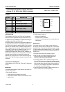
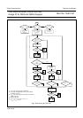
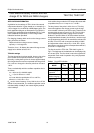
The flow chart of the TEA1104; TEA1104A is given in
Fig.5. The load state of the batteries can be displayed by
one or two LEDs. The flow chart is not to be regarded as
sequential. Each mode of operation is a purely separate
continuous process.
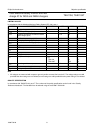
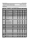
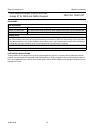
Table 1 Dual LED indication
CHARGER
MODE
V
LED
V
S
LED 1 LED 2
Fast charging low high on off
Fast charging
protection
low/high high on/off off
Full
(trickle charging)
low/high low off on
Battery open high high off off