PS5580 RS232 and LAN Command Protocol 14
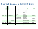
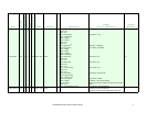
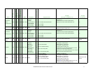
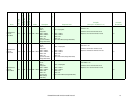
Screen V Position 0x37 Y W 4 3 0x02 = Write
Byte 1: V Position
(Range 0x00-0x64)
4
Byte 1: V Position (Range 0x00-0x64) Write 50 (0x32):
Command: 02 37 04 01 04 02 32 03
Response: 02 37 04 01 04 02 32 89 03
Write 50 (0x32)
Command: 02 37 03
00 00 32 03
Serial Control
(LAN Off)
0x71 Y W 3 2 0x02 = Write [None] 3
[None] Command: 02 71 03 01 04 02 03
Response: 02 71 03 01 04 02 82 03
Command: 02 71 02
00 00 03
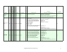
Serial Control
(LAN On)
0x70 Y W 3 2 0x02 = Write [None] 3
[None] Command: 02 70 03 01 04 02 03
Response: 02 70 03 01 04 0283 03
Command: 02 70 02
00 00 03
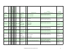
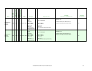
Sharpness 0x22 Y W 4 3 0x02 = Write
Byte 1: Sharpness
(Range 0x00-0x18)
4
Byte 1: Sharpness (Range 0x00-0x18) Write 50 (0x32):
Command: 02 22 04 01 04 02 32 03
Response: 02 22 04 01 04 02 32 9E 03
Write 50 (0x32)
Command: 02 22 03
00 00 32 03
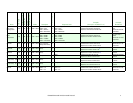
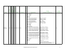
Test Pattern
Mode
0xE7 Y W 4 3 0x02 = Write
Byte 1: Test Pattern
- 0x00 = Disabled
- 0x01 = White
Pattern
4
Byte 1: Test Pattern
- 0x00 = Disabled
- 0x01 = White Pattern
Test Pattern = White Pattern:
Command: 02 E7 04 01 04 02 01 03
Response: 02 E7 04 01 04 02 01 0A 03
Test Pattern = White
Pattern:
Command: 02 E7 03
00 00 01 03
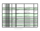
Tiling Menu Lock
Configuration
0xB3 Y W 4 3 0x02 = Write
Byte 1: Tiling Lock
- 0x00 = Lock
disabled
- 0x01 = Lock
enabled
4
Byte 1: Tiling Lock
- 0x00 = Lock disabled
- 0x01 = Lock enabled
Tiling Lock = Enabled:
Command: 02 B3 04 01 04 02 01 03
Response: 02 B3 04 01 04 02 01 3E 03
Tiling Lock = Enabled:
Command: 02 B3 03
00 00 01 03
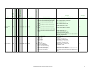
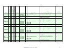
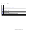
Tint 0x24 Y W 4 3 0x02 = Write
Byte 1: Tint (Range
0x4D-0xB1)
4
Byte 1: Tint (Range 0x4D-0xB1) Write 0 (0x7F):
9
Command: 02 24 04 01 04 02 7F 03
Response: 02 24 04 01 04 02 7F 4F 03
Write 0 (0x7F)
Command: 02 24 03
00 00 7F 03
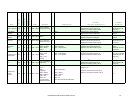
White Balance
Control:
Blue Gain
0xBE N W 5 N/A 0x02 = Write
Byte 1: Input
Source
- 0x01 =
DisplayPort
- 0x02 = HDMI 1
- 0x03 = HDMI 2
- 0x04 = DVI
- 0x05 = PC
Byte 2: Blue Gain
(Range 0x00-0x64)
5
Byte 1: Input Source
- 0x01 = DisplayPort
- 0x02 = HDMI 1
- 0x03 = HDMI 2
- 0x04 = DVI
- 0x05 = PC
Byte 2: Blue Gain (Range 0x00-0x64)
Input Source = PC
Blue Gain = 50
Command: 02 BE 05 01 04 02 05 32 03
Response: 02 BE 05 01 04 02 05 32 FC 03
N/A
Name
Command
Broadcast Supported
Read/Write
Length
Length (Broadcast
Mode Data Bytes
Response Length
Response Data
Example
(Group ID = ‘A’, Multi ID = 4)
Example
(Broadcast)


