


PS5580 RS232 and LAN Command Protocol 8
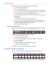
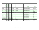
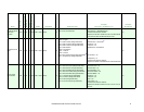
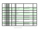
Get Model Name
and Serial
Number
0xB9 N R 3 N/A 0x00 = Read [None] 25
Bytes 1-9: Model Name
Bytes 10-22: Serial Number
Model Name = PS5580
Serial Number = ABCDEFGHIJKLM
Command: 02 B9 03 01 04 00 03
Response: 02 B9 19 01 04 00 50 53 35 35 38 30 00 00 00
41 42 43 44 45 46 47 48 49 4A 4B 4C 4D 16 03
N/A
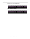
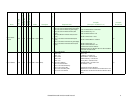
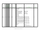
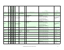
Get OSD Control
Data
0x98 N R 3 N/A 0x00 = Read [None] 10
Byte 1: OSD Language
- 0x00 = English
Byte 2: OSD Timeout (Range 0x05-0x78)
Byte 3: OSD H Position (Range 0x00-0x64)
Byte 4: OSD V Position (Range 0x00-0x64)
Byte 5: OSD Rotation
- 0x00 = No Rotation
- 0x01 = H Mirror
- 0x02 = V Mirror
Byte 6: Info Timeout (Range 0x00, 0x03-0x0A)
4
Byte 7: Transparency (Range 0x00-0x0F)
OSD Language = 0
OSD Timeout = 10 seconds
3
H Position = 50
V Position = 50
OSD Rotation = No Rotation
Info Timeout = 10
Transparency = 0
Command: 02 98 03 01 04 00 03
Response: 02 98 0A 01 04 00 00 0A 32 32 00 0A 00 DE 03
N/A
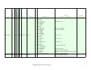
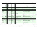
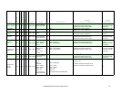
Get PC Setup
Control Data
0x96 N R 3 N/A 0x00 = Read [None] 13
Byte 1: ADC Red Gain (Range 0x00-0x64)
Byte 2: ADC Green Gain (Range 0x00-0x64)
Byte 3: ADC Blue Gain (Range 0x00-0x64)
Byte 4: ADC Red Offset (Range 0x00-0x64)
Byte 5: ADC Green Offset (Range 0x00-0x64)
Byte 6: ADC Blue Offset (Range 0x00-0x64)
Byte 7: H Position (Range 0x00-0x64)
Byte 8: V Position (Range 0x00-0x64)
Byte 9: Clock (Range 0x00-0x64)
Byte 10: Clock Phase (Range 0x00-0x3F)
ADC Red Gain = 51
ADC Green Gain = 52
ADC Blue Gain = 53
ADC Red Offset = 49
ADC Green Offset = 48
ADC Blue Offset = 47
H Position = 50
V Position = 50
Clock = 50
Clock Phase = 32
Command: 02 96 03 01 04 00 03
Response: 02 96 0D 01 04 00 33 34 35 31 30 2F 32 32 32
20 73 03
N/A
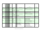
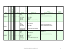
Name
Command
Broadcast Supported
Read/Write
Length
Length (Broadcast
Mode Data Bytes
Response Length
Response Data
Example
(Group ID = ‘A’, Multi ID = 4)
Example
(Broadcast)