


8
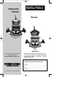
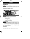
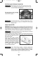
ATTACHING THE MOTOR TO THE ROUTER BASE
DISCONNECT TOOL FROM POWER SOURCE.
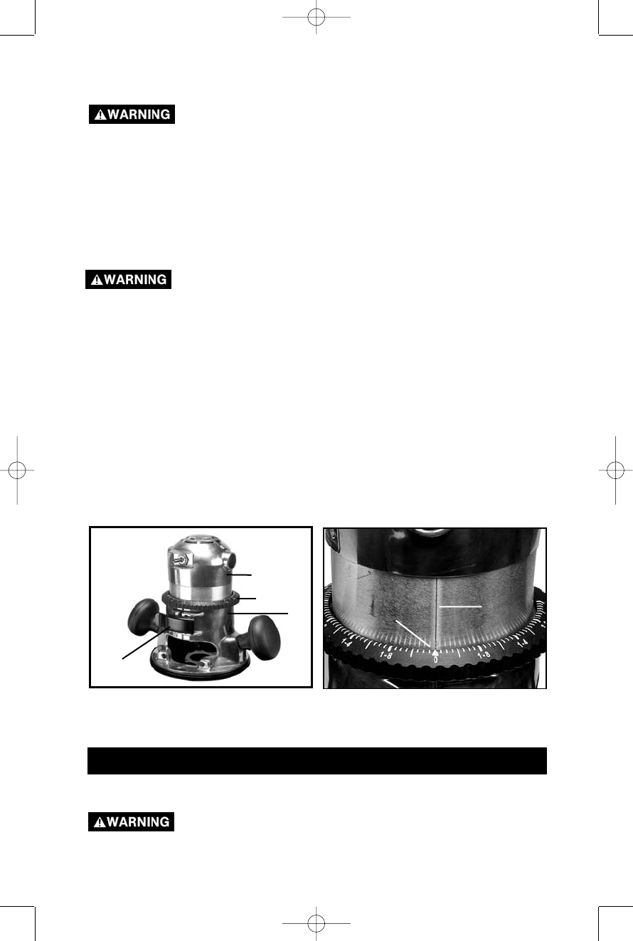
1. Open the clamp (A) Fig. 1 and set the power unit in the base unit.
2. Align the lower pin of the power unit (B) Fig. 1 with the groove in the base.
3. Rotate the power unit CLOCKWISE into the base until the upper guide
pins are set in the groove of the base.
4. Close the clamp.
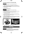
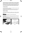
ADJUSTING DEPTH OF CUT
DISCONNECT TOOL FROM POWER SOURCE.
1. Open the clamp (A) Fig. 3A.
2. Hold the base (E) and turn the power unit (F) Fig. 3A COUNTER-CLOCK-
WISE until the tip of the bit is above the bottom of the base.
3. Set the tool on a flat surface.
4. Turn the power unit (F) Fig. 3A CLOCKWISE until bit touches the work.
5. Close the clamp (A) Fig. 3A.
6. Rotate the depth adjusting ring (B) Fig. 3A until the zero-line (C) Fig. 3B is
opposite the index line (D) Fig. 3B on the housing.
7. Open the clamp (A) Fig. 3A.
8. Tip the router so that the bit is clear of the wood surface. Turn the power
unit (F) Fig. 3A CLOCKWISE until the index line (D) Fig. 3B on the motor
housing reaches the desired depth indicated on the ring.
9. Close the clamp (A) Fig. 3A.
NOTE: Setting the index line to 1/4" on the ring means the cutting
edge of the bit is exposed 1/4" below the base.
CONNECTING TO POWER SOURCE
Before connecting tool to power source ALWAYS MAKE
SURE SWITCH IS IN THE “OFF” POSITION. Also check
that the power circuit is the same as that shown on
specification plate of the router.
Fig. 3A
F
E
A
B
C
D
Fig. 3B
OPERATION
907395 - 12-20-02.qxd 12/20/02 9:13 AM Page 8