


8
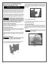
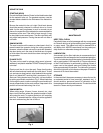
Replace if 3/16"
(4.7mm) or less
at either end.
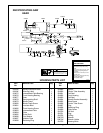
DISASSEMBLY
HANDLE
Should the throttle valve seal 847426, need replacing,
unscrew the throttle valve cap 867753, for removal of the
throttle valve and components.
The tool is equipped with an air screen for protection of the
internal motor parts from foreign material. The air screen
located in the inlet bushing may be removed for cleaning
and inspection by unscrewing the inlet bushing 867758. If
the screen is torn or damaged, the inlet bushing should be
replaced. The throttle handle and motor housing, may be
removed for cleaning and inspection by unscrewing the two
(2) socket head cap screws and nuts after the tool is
disassembled to the point that the motor can be removed
to allow access to nuts inside motor housing.
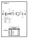
MOTOR HOUSING & MOTOR
The front housing and intermediate plate 204683, must be
removed from motor housing to remove motor. Remove
four (4) hex cap screws holding the front housing and
intermediate plate to motor housing. The motor can be
pulled from motor housing. The "O"-rings and mufflers can
be removed from motor.
Use a suitable driver to drive the front rotor shaft out of the
front rotor bearing. After removing the cylinder and rotor
blades, the rear rotor shaft may be driven out of the rear
rotor bearing.
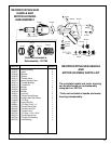
FRONT HOUSING & INTERMEDIATE PLATE
To disassemble the front housing 204692, from the inter-
mediate plate 204683, remove (4) four hex cap screws and
lift complete unit off the intermediate plate. The secondary
muffler can be removed for inspection.
REASSEMBLY
The tool is reassembled in the reverse order of disassem-
bly. Inspect all parts for damage or wear. It is recommended
that new rotor blades be installed at each repair cycle. If not
replaced, the used ones must measure a minimum of 3/16"
(4.7mm) at both ends.
Replace bearings that are rough or have excessive end
play. Install the front rotor bearing in the front bearing plate
and measure the distance from the face of the bearing plate
to the inner race of the bearing with the bearing race loaded
rearward. Select or fit by sanding, a rotor collar .001"
(.025mm) to .002" (.050mm) longer than this measure-
ment. Install the rotor blades, cylinder rear bearing plate,
and rear bearing on the rotor. After final assembly of the
motor unit, the cylinder should be held securely but not
tightly between the two plates. The rotor should not rub
either plate.
Note: Tighten 204727 locknuts holding handle to backhead,
to a maximum of 12 ft. lbs. of torque during reassembly.
Tighten all screws and nuts securely during reassembly.
Place a few drops of 10W machine oil in the air inlet to
ensure positive lubrication of all motor parts as soon as air
is applied.