9
ATTACHING THE AUXILIARY HANDLE
Hold the auxiliary handle as illustrated in Fig. 6. This grip
helps you resist the rotational force and prevents accidental electrical
shock, should you accidentally drill into a live wire. Use the auxiliary
handle during all drilling operations.
Disconnect tool from power source.
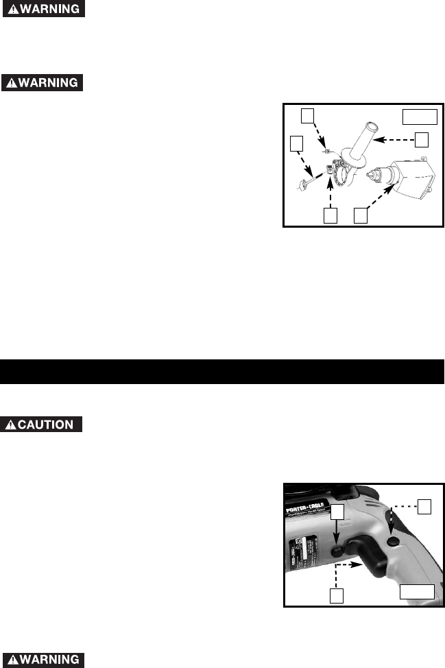
1. Insert the square nut (A) Fig. 3 into the
recess in the auxiliary handle (B).
2. Position the clamping plate (C) on the
auxiliary handle with the serations over
the hex opening.
3. Insert the clamping screw (D) through
the clamping plate (C) and the auxiliary
handle (B), and thread it into the nut (A).
Do not tighten completely.
4. Slide the auxiliary handle assembly over the chuck and on the front of
the housing.
5. Locate the handle in the desired position and align the recesses in the
handle to engage the bosses (F) Fig. 3 on the housing. The handle may
be located in any one of 12 positions 360° around the housing.
6. Tighten the clamping screw (D) securely.
A
B
C
D
E
TO START AND STOP THE DRILL
Confirm that the switch is “OFF”. Make sure that the power
circuit voltage is the same as that shown on the specification plate. Connect
the drill to the power circuit.
1. Squeeze the trigger switch (A) Fig. 4 to start the motor. Release the
trigger to stop the motor.
2. A lock button (B) Fig. 4 is provided to
keep motor running without holding the
trigger switch “ON”. To lock the trigger
switch “ON”, squeeze the trigger as far
as it will go, push in the lock button and
release the trigger. To unlock the lock
button, squeeze the trigger and release,
leaving the lock button free to spring out.
NOTE: The lock button can be engaged ONLY when the drill is running at
maximum speed.
Never use the lock button when the drill may have to be
stopped suddenly.
Fig. 3
OPERATION
A
C
B
Fig. 4


