


6
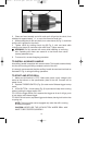
3. Clean and insert smooth end of bit as far as it will go into the chuck, then
withdraw bit approximately
1
/16", or up to the flutes for small bits.
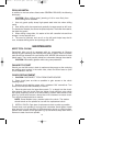
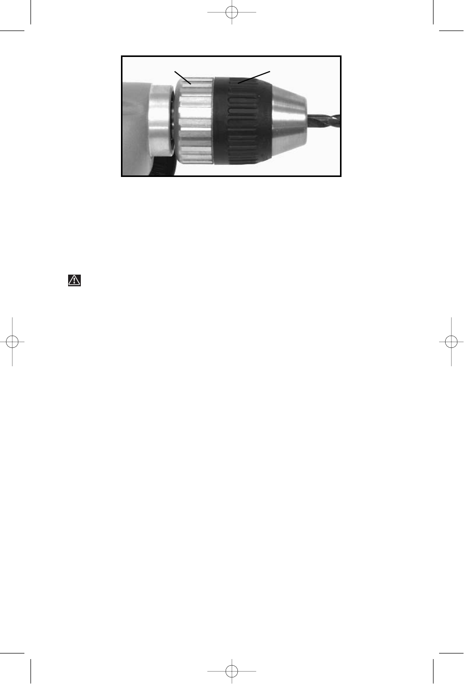
4. While holding the bit with one hand, turn outer sleeve (A) Fig. 2, clockwise
until the bit is gripped in the chuck.
5. Tighten chuck by holding chuck ring (B) Fig. 2, with one hand while
turning outer sleeve (A) clockwise with other hand. Tighten securely.
WARNING: Do not operate drill motor while installing or removing
bits. Operating drill motor can cause bit to be thrown from chuck
causing personal injury.
6. To remove bit, reverse foregoing procedure.
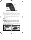
TO INSTALL AUXILIARY HANDLE
An auxiliary handle is supplied with some models. This handle screws directly
into the drill housing providing complete control of the drill.
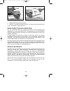
It is strongly recommended that the auxiliary handle be used and tool held as
illustrated in Fig. 4 during all drilling operations.
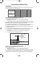
TO START AND STOP DRILL
1. Make sure drill switch is “OFF”. Make sure power circuit voltage is the
same as that shown on the specification plate of the drill. Connect drill to
power circuit.
2. Squeeze TRIGGER SWITCH (Fig. 3) to start motor. Release trigger to stop
motor.
3. LOCK BUTTON – A lock button (Fig. 3) is provided to keep motor running
without holding the trigger switch ON.
TO LOCK the trigger switch ON, squeeze the trigger as far as it will go, push
in lock button and release trigger.
TO UNLOCK lock button, squeeze trigger and release, leaving lock button free
to spring out.
NOTE: The lock button can be engaged only when the drill is running
at maximum speed.
CAUTION: NEVER USE THE LOCK BUTTON WHERE DRILL MAY
HAVE TO BE STOPPED SUDDENLY.
Fig. 2
AB
901013 - 12-31-01.qxd 2/11/02 3:01 PM Page 6