


6
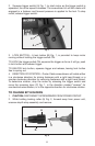
3. Pull bit holder (B) Fig. 2, with bit straight out. If it is difficult to remove,
grip with pliers and pull. NOTE: Bit (C) Fig. 2, may be removed from bit holder
by pulling straight out.
4. Push new bit holder in spindle until ball in spindle snaps in groove in bit
holder.
5. Screw on depth stop assembly (D) Fig. 2, and readjust (see TO ADJUST
DEPTH STOP).
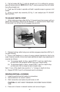
TO ADJUST DEPTH STOP
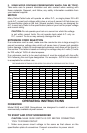
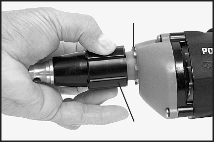
1. While holding locking collar (A) Fig. 3, forward away from power unit turn
depth stop assembly until end of bit extends
3
/32
" beyond end of depth stop.
Do not push in on bit as this will engage internal drive.
2. Release locking collar being sure notches engage projections (B) Fig. 3,
on gear housing.
3. Drive a test fastener in a piece of scrap material identical to that to be
used. Examine results of drive and make additional depth stop adjustment if
required as follows:
(a) To increase depth of drive, repeat STEP 1 and turn depth stop
so that end of bit extends further from end of depth stop.
(b) To decrease depth of drive, repeat STEP 1 and turn depth stop
so that end of bit is closer to end of depth stop.
Each
1
/4 turn of the depth stop results in
1
/64" change in depth of drive.
4. Repeat STEPS 2 and 3 until desired result is obtained.
DRIVING DRYWALL SCREWS
1. Install drywall bit and bit holder to screwdriver.
2. Set screwdriver for correct rotation.
3. Start screwdriver and place drywall screw on bit.
CAUTION: DO NOT EXERT PRESSURE ON SCREW WHILE DOING
THIS.
4. Place end of screw in desired location and remove fingers.
Fig. 3
A
B