


8
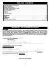
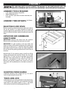
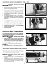
ELEVATING CRANK HANDLE
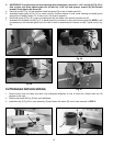
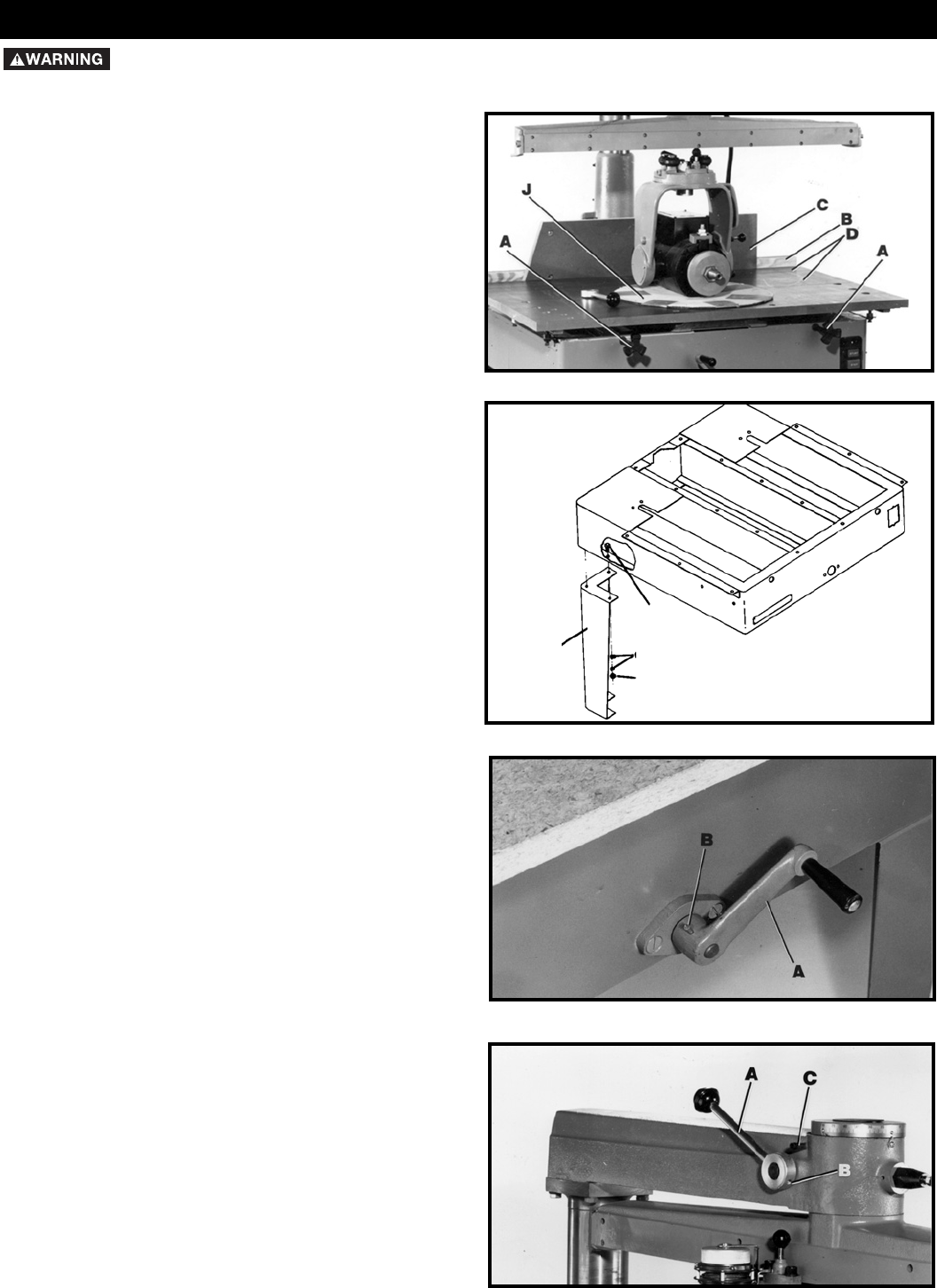
Assemble elevating crank handle (A) Fig. 6 to rod in
front of base using the roll pin (B).
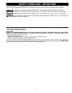
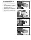
TRACK-ARM LOCK
Assemble track-arm lock handle (A) to the overarm (Fig.
7), and tighten set screw (B). Lock handle (A) should be
tight when in the position shown in Fig. 7, and loose
when pulled forward and resting against stop (C).
Fig. 6
Fig. 7
ASSEMBLY
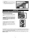
SELECTING FLOOR SPACE
Before unpacking, determine exactly where you want to
set up the machine. It is highly desirable to locate the
machine against the wall where it will be out of the way
and will actually facilitate material handling through the
shop.
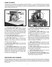
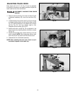
UNPACKING AND ASSEMBLING
LEGS TO BASE
IMPORTANT: Remove the carton from the machine.
Remove bolts that fasten the machine to the skid.
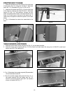
IMPORTANT: To gain access to the four bolts that
fasten the saw to the wooden shipping skid, loosen two
table lock knobs (A) Fig. 4. Remove fence (B), angled
front table board (C) and at least two table boards (D).
Do not remove the packing material around the motor at
this time.
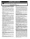
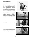
Mechanically lift the machine using a forklift and lifting
straps, and support the machine. Attach the four steel
legs (E) Fig. 5, to each corner of the base using twelve
3/8-16x1" hex head screws (F), 3/8" flat washers (G),
and 3/8" lockwashers (I) and 3/8-16 hex nuts (H).
Remove the packing material from around the motor.
The motor will be positioned on the table as shown in
Fig. 4.
Fig. 4
Fig. 5
E
F
G
H
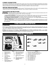
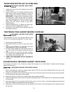
ASSEMBLY TOOLS REQUIRED
ASSEMBLY TIME ESTIMATE-
4 to 6 hours
* 1/16" Open End Wrench (supplied)
* Roller Head Wrench (1)
* 9/16” and 3/8” open end or socket wrenches (not
included)
FOR YOUR OWN SAFETY, DO NOT CONNECT THE MACHINE TO THE POWER SOURCE UNTIL THE
MACHINE IS COMPLETELY ASSEMBLED AND YOU READ AND UNDERSTAND THE ENTIRE INSTRUCTION MANUAL.