


11
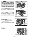
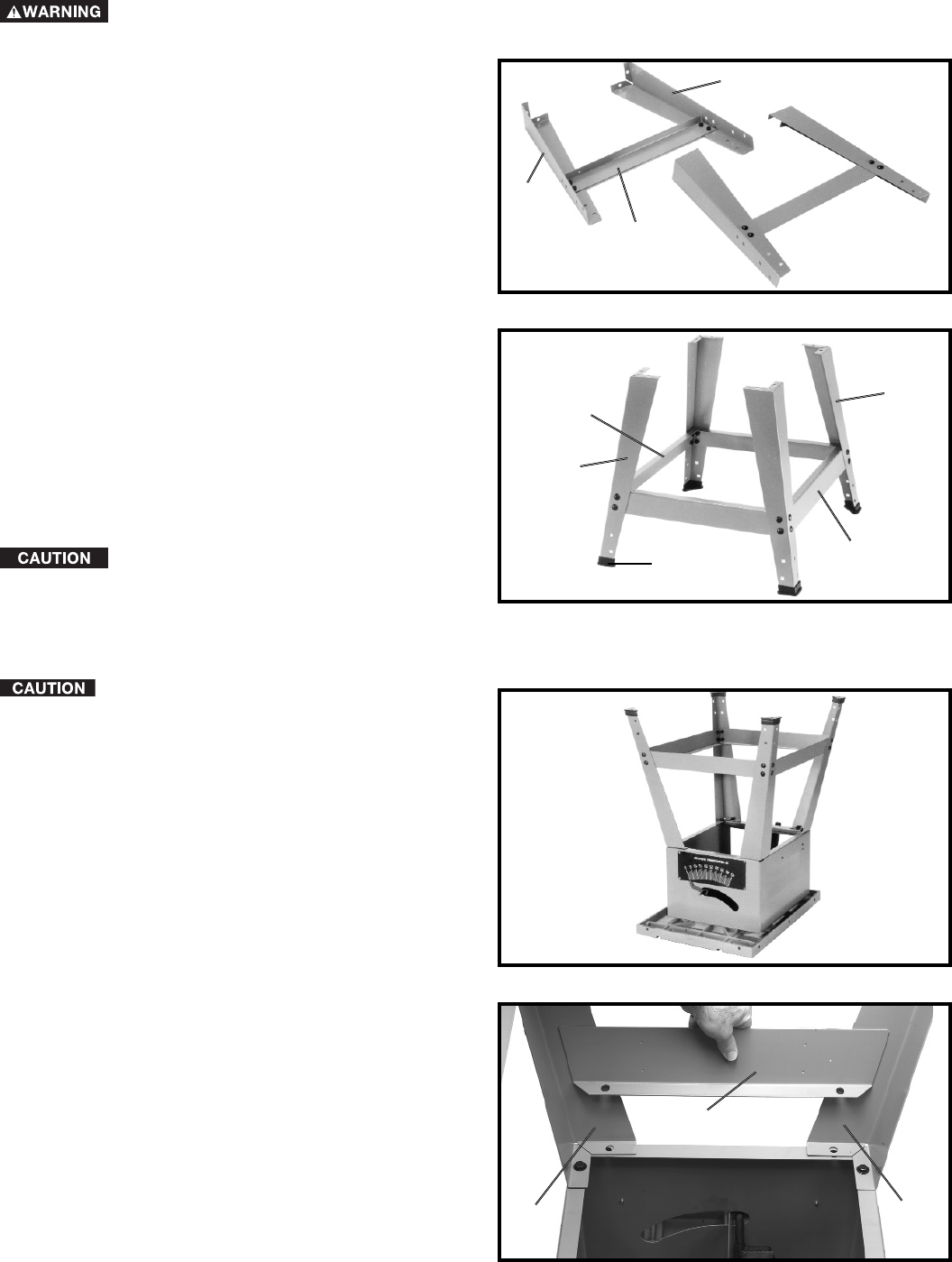
STAND LEGS
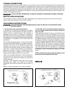
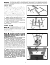
1. Assemble the longer bottom bracket (A) Fig. 6, to
the inside of two table legs (B) as shown. Align the holes
in the longer bottom bracket (A) Fig. 6, with the holes in
the table legs (B). Insert a 5/16-18x5/8" carriage bolt
through the holes in the leg (B) and the hole in the longer
bottom bracket (B). Place a 5/16" flat washer, then a
5/16" lockwasher on the carriage bolt, and fasten with a
5/16-18 hex nut. NOTE: Only finger tighten stand
mounting hardware at this time. Repeat this process for
the three remaining holes in the larger bottom bracket.
2. Assemble the other stand bracket (A) Fig. 6, to the
remaining two table legs (B) in the same manner.
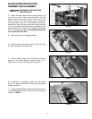
3. Assemble the two shorter stand brackets (D) Fig. 7,
to the leg assemblies (B) in the same manner as the
longer bottom bracket was assembled.
4. Assemble a plastic foot (E) Fig. 7, to the bottom of
each leg as shown.
Fig. 6
Fig. 7
Fig. 8
B
B
A
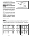
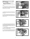
FOR YOUR OWN SAFETY, DO NOT CONNECT THE MACHINE TO THE POWER SOURCE UNTIL
THE MACHINE IS COMPLETELY ASSEMBLED AND YOU READ AND UNDERSTAND THE ENTIRE
INSTRUCTION MANUAL.
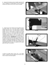
Fig. 9
H
D
D
D
B
E
D
B
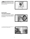
STAND TO SAW
TO PREVENT PERSONAL INJURY OR
DAMAGE TO THE MACHINE, WE
SUGGEST THAT THE STAND BE MOUNTED TO THE
SAW AS FOLLOWS:
1. Place the saw upside down on a sturdy work bench
or floor as shown in Fig. 8.
TO PROTECT THE TABLE TOP, PLACE
SOMETHING BETWEEN THE TABLE TOP AND THE
WORK BENCH OR FLOOR, SUCH AS A PIECE OF
CARDBOARD, CARPET ETC.
NOTE: Make certain the shorter stand brackets (D) Fig.
8, are at the front and rear of the saw as shown.
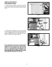
2. Align the eight holes in the bottom of the saw
cabinet with the eight holes in stand legs. Place a 5/16"
flat washer on a 5/16-18x5/8" hex head screw. Insert the
hex head screw through the hole in the saw cabinet and
the hole in the stand leg. Place a 5/16" flat washer, then
a 5/16" lockwasher on the hex head screw, and fasten
with a 5/16-18 hex nut. NOTE: Only finger tighten stand
mounting hardware at this time. Repeat this process for
the five remaining holes in the saw cabinet and the stand
legs.
3. Assemble bracket (H) Fig. 9, to the inside of front leg
assembly (D) as shown. Align holes in bracket (H) with
holes in front leg assembly (D). Place a 5/16" flat washer
on a 5/16-18x5/8" hex head screw. Insert the hex head
screw through the hole in the saw cabinet, stand leg,
and bracket (H). Place a 5/16" flat washer then a 5/16"
lockwasher on the hex head screw, and fasten with a
5/16-18 hex nut. NOTE: Only hand tighten stand
mounting hardware at this time.