


12
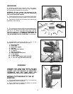
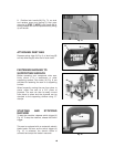
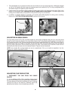
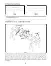
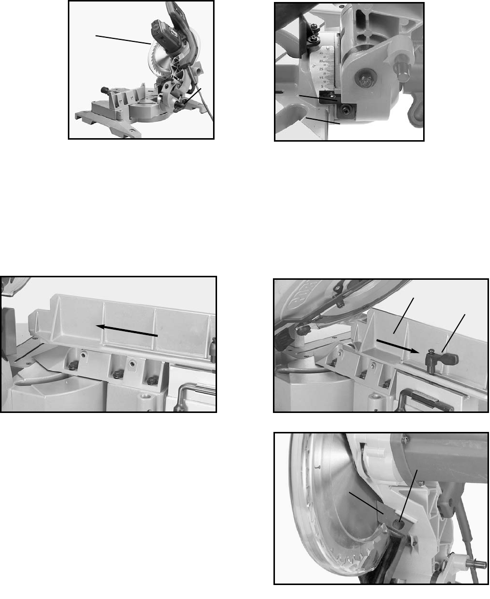
1. The cuttinghead of your compound miter saw can be tilted to cut any bevel angle from a 90 degree straight
cut-off to a 45 degree left bevel angle by loosening bevel lock handle (A) Fig. 23, tilting cuttinghead (B) to
the desired angle, and tightening lock handle (A).
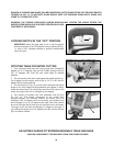
2. Positive stops are provided to rapidly position the saw blade at 90 and 45 degrees to the table. Refer to the
section of this manual titled “Adjusting 90 and 45 degree bevel positive stops.” The bevel angle of the
cutting arm is determined by the position of the pointer (C) Fig. 24, on scale (D).
3. In addition, a marked indicator is provided on the bevel scale (33.9 degrees) for cutting crown moulding.
Refer to the “CUTTING CROWN MOULDING” section of this manual.
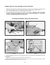
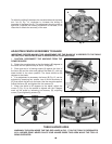
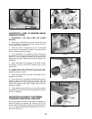
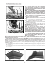
ADJUSTING SLIDING FENCE
The high sliding fence (A) Fig. 25A, provides support for extra large workpieces used with your saw and should
always be set as close as possible to the saw blade. When miter cutting (blade set 90 degrees to the table and
at an angle to the right or left), the fence should be set all the way toward the blade, (Fig. 25A). When bevel cutting,
however (blade tilted at an angle to the table), the fence (A) Fig. 25B, should be moved away from the blade to
allow for proper clearance for the saw blade and guard, (Fig. 25B). To accomplish this movement, loosen the lock
handle (B), and slide the fence (A) to the desired location. Tighten the lock handle (B).
NOTE: Lock handle (B) is spring-loaded and can be repositioned. Pull up on handle to reposition it on the
serrated nut located underneath handle.
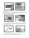
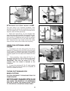
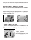
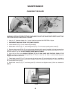
ADJUSTING CHIP DEFLECTOR
1. DISCONNECT THE SAW FROM THE POWER
SOURCE.
2. A chip deflector (A) Fig. 26, is supplied to help prevent
scrap or cut-off pieces from entering the upper blade guard.
The chip deflector (A) should be adjusted so that it is almost
touching the side of the blade by loosening screw (B),
adjusting chip deflector (A) and tightening screw (B).
Fig. 26
B
Fig. 25A
Fig. 25B
B
A
Fig. 23
A
B
Fig. 24
D
C
A