13
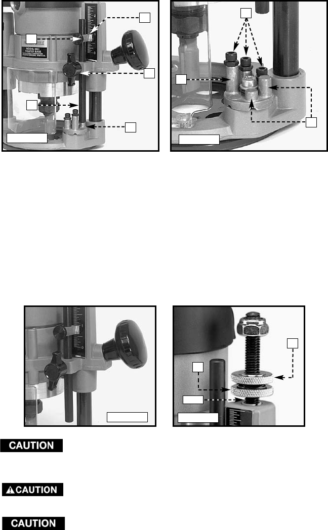
2. Release plunge mechanism by pulling the locking lever (B) Fig. 9 to the
left. Lower the plunge mechanism until the router bit touches the work
surface. Release the lever and push it to the right to lock the mechanism
in this position.
3. Tighten depth-rod locking knob.
4. Position depth indicator (C) Fig. 10 at the “0” position and tighten the
knob.
5. Loosen depth-rod locking knob (A) Fig 10, and raise until indicator aligns
with the graduation representing the desired depth of plunge. (The
example in Fig. 12 shows setting for 1" plunge.)
6. Turn lower-travel limiting nut (A) Fig. 13 until it is approximately 1/4"
above the top of the plunge housing (Fig. 13). While holding lower nut,
turn upper nut until it “jams” against the lower nut.
The travel limiting nuts must always be “jammed” together
to prevent movement (caused by vibration) which could
prevent full bit retraction.
The travel limiting nuts must always be set so that bit can be
retracted into the base of the router, clear of the workpiece.
DO NOT attempt to increase the plunge travel by
readjusting the stop nut. Increasing the travel beyond
2-1/2" can cause the mechanism to jam.
Fig. 10
Fig. 11
Fig. 12
Fig. 13
D
C
A
E
B
C
B
A
B
A
1-1/4"


