7
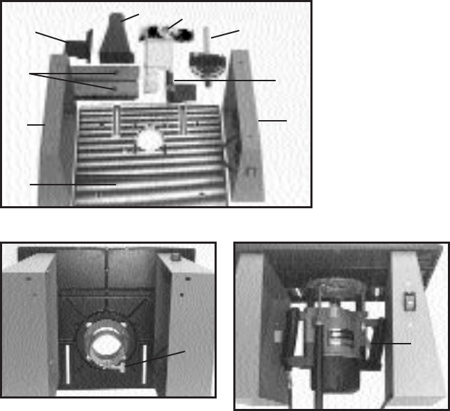
4. Mount the router base (see Fig. 6 for non-plunge routers, or Fig. 7 for
plunge routers), to the underside of the table using screws from the hardware
package (routers with less than 2 horsepower use three #10-24 x
3
… 4" long
screws, routers with more than 2 horsepower except Model 7529 use four
5
… 16"-18 x 1
1
… 4" screws, and Model 7529 uses three 10-24 x
11
…16" screws).
Orient the router base directly below the large hole in the table, with the clamp
screw (A) Fig. 6, (or the plunge locking lever (A) Fig. 7, on plunge models),
toward the rear of the table.
NOTE: The router sub-base must be removed before mounting to
table.
5. Place router motor into base and tighten clamp screw to secure (non-
plunge models only).
6. Position the rear cutter guard (A) Fig. 8, to the right fence bracket and
top cutter guard assembly. Secure with two #10-32 x
3
… 8" screws.
NOTE: The rear cutter guard also provides a 2
1
… 2" diameter dust
collection port.
7. Position the right hand (in-feed) fence bracket and guard assembly (A)
Fig. 9, to the slot on the right side of the table. Insert a
5
… 16"-18 x 1
1
… 4"
carriage bolt (from the hardware package), up through the table and the fence
bracket. Secure by threading on one of the black knobs.
Fig. 5
A
D
B
C
F
H
G
J
E
A Left Leg
B Right Leg
C Table
D Left Fence Bracket
E Right Fence Bracket/
Guard Assembly
F Fence (2)
G Rear Cutter Guard/
Dust Port
H Hardware Package
J Miter Gage
Fig. 6
A
Fig. 7
A


