


16
Fig. 27
Fig. 28
Fig. 29
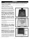
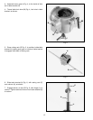
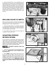
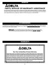
DRILLING HOLES TO DEPTH
Where a number of holes are to be drilled to exactly the
same depth, a depth stop is provided in the pinion shaft
housing (A) Fig. 27, and is used as follows:
1. Loosen lock lever (B) Fig. 27, and rotate housing (A)
until the pointer (C) lines up with the depth indicated on
the English/Metric scale (D) that you want the spindle to
lower. Then tighten lock lever (B).
2. The spindle will then lower to the exact depth as
indicated on the scale (D) Fig. 27
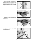
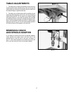
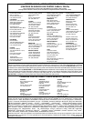
ADJUSTING SPINDLE
RETURN SPRING
For the purpose of automatically returning the spindle
upward after a hole has been drilled, a spindle return
spring is provided in the spring housing (A) Fig. 28. This
spring has been properly adjusted at the factory and
should not be disturbed unless absolutely necessary. To
adjust the return spring, proceed as follows:
DISCONNECT MACHINE FROM THE
POWER SOURCE.
1. Loosen the two nuts (B) Fig. 28, approximately one-
quarter inch. IMPORTANT: DO NOT REMOVE NUTS
(B) FROM SHAFT.
2. While FIRMLY holding spring housing (A) Fig. 28,
pull out housing and rotate it until the roll pin (C) is
engaged with the next notch on the housing. Turn the
housing counterclockwise to increase and clockwise to
decrease spring tension. Then tighten the two nuts (B)
to hold the housing in place. IMPORTANT: NUTS (B)
SHOULD NOT CONTACT SPRING HOUSING (A) WHEN
TIGHT.
B
C
A
D
B
A
C
B
A
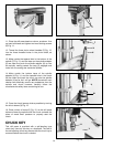
Fig. 26
A
C
B
D
D
E
F
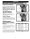
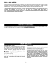
5. After the belts (D) Fig. 26, are positioned on the
desired steps of the motor, center and spindle pulleys,
move tension lever (C) to the rear until the belts (D) are
properly tensioned and tighten the two tension lock
knobs (B). The belts (D) should be just tight enough to
prevent slipping. Excessive tension will reduce the life of
the belts, pulleys and bearings. Correct tension is
obtained when the belts (D) can be flexed about 1″ out
of line midway between the pulleys using light finger
pressure.