


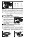
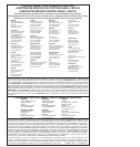
Fig. 3A
A
9
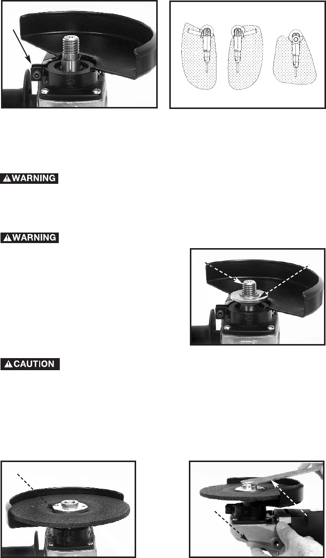
Fig. 4
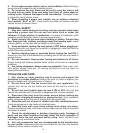
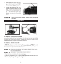
3. Seat the guard on the mounting flange. Rotate the guard to a position
that will place the guard between the operator and the grinding wheel (or
any other accessory requiring a guard). Tighten the clamp screw (A) Fig. 3A
to secure the guard in proper position (see Fig. 4).
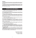
Always make sure that the wheel guard is positioned between
the operator and the wheel, so that flying chips or pieces of a
wheel that might break will be deflected away from the
operator (see Fig. 4).
TO INSTALL GRINDING WHEEL
DISCONNECT TOOL FROM POWER CIRCUIT.
1. Rest the tool on its back with the
spindle facing up.
2. Install and adjust the appropriate
wheel guard following instructions in
“TO INSTALL WHEEL GUARD”
section of this manual.
3. Position the inner flange (A) Fig. 5 on
the spindle (C) with the round hub
facing outward, away from machine.
Rotate the flange until it drops into
place on the spindle.
Use Type 1 Wheel Guard when using Type 1 Wheels.
4. Place the grinding wheel on the spindle.
5. Place the outer flange (B) Fig. 6 on the spindle with the flat side against
the wheel and thread into place hand-tight.
6. Depress the spindle lock pin (E) Fig. 7, and hold while rotating the
grinding wheel clockwise by hand until the spindle lock engages.
7. Continue holding the spindle lock pin while placing the lugs of the
spanner wrench (F) Fig. 7 into the holes of the outer flange. Tighten
securely by turning clockwise.
Fig. 5
A
C
Fig. 6
Fig. 7
E
F
B