


8
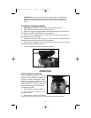
INSTALLATION:
1. Insert threaded end of handle into handle clamp (A) Fig. 1A.
2. Turn handle clockwise and tighten securely.
CHANGING POSITIONS:
1. Loosen handle by turning 2 full turns counterclockwise.
2. Push in on handle and move handle to
desired location.
3. Release handle.
4. Retighten securely.
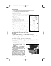
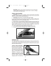
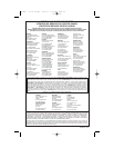
TO INSTALL SANDING DISC
1. CAUTION: DISCONNECT MACHINE
FROM POWER CIRCUIT.
2. Rest machine on its back with spindle
facing up.
3. Position inner flange (B) Fig. 2, onto
spindle (A), with round hub facing outward,
away from machine. Rotate flange until it drops
into place on the spindle.
4. Place back-up pad (C) Fig. 2, onto spindle
and rotate clockwise until seated.
5. Depress spindle lock button (D) Fig. 2,
rotate back-up pad (C) clockwise until spindle
lock engages, and firmly tighten back-up pad. Continue to depress spindle
lock button.
6. Place sanding disc (E) Fig. 2, on back-up pad and center it.
7. Place retaining nut (F) Fig. 2, through hole in sanding disc. Tighten
securely by turning clockwise.
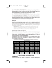
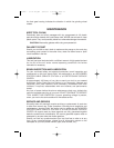
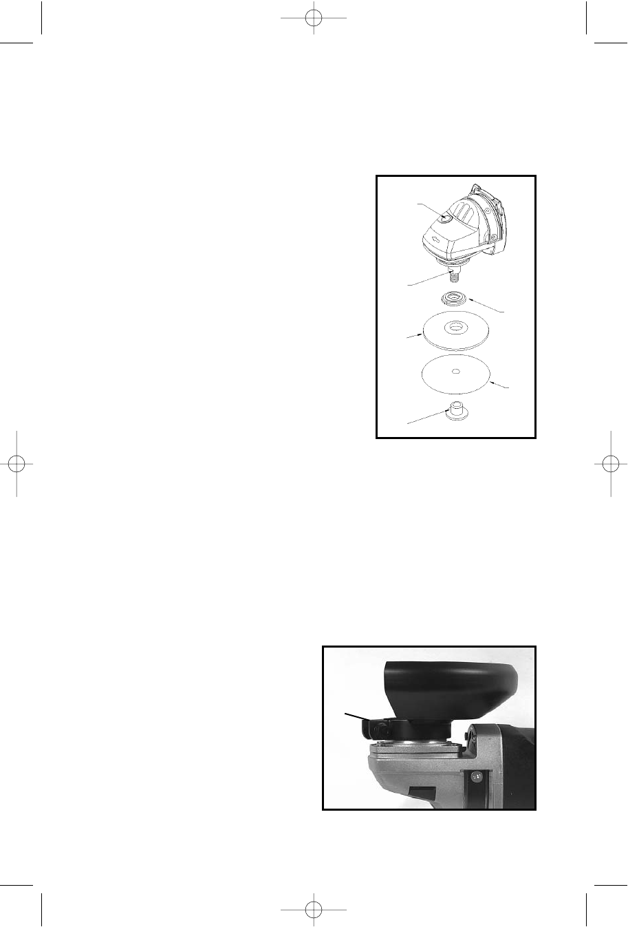
TO INSTALL WHEEL GUARD (ACCESSORY)
There are 7" or 9" TYPE 27 wheel guards available as accessories. (See the
ACCESSORIES Section of this manual for specific applications). Both guards
are installed and adjusted in the same manner.
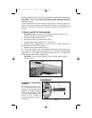
WARNING: Always use an approved, and properly adjusted wheel
guard where required (see
ACCESSORIES Section of this
manual).
1. CAUTION: DISCONNECT
MACHINE FROM POWER CIRCUIT.
2. Rest machine on its back with
spindle facing up.
3. Seat guard onto mounting flange.
Rotate the guard to a position that
will place the guard between the
operator and the grinding wheel (or
other accessory requiring a guard).
Tighten clamp screw (A) Fig. 3, to
secure the guard in proper position.
D
Fig. 2
A
Fig. 3
A
B
C
E
F
283800 - 07-31-00.QXD 9/23/02 1:34 PM Page 8