


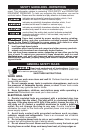
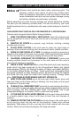

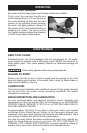
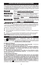
3. Push forward on the switch
release lever (A) Fig. 1 as you
squeeze the switch paddle (B) to
turn the tool “ON”.
4. Release, the switch paddle to
return to the "OFF" position.
Allow the tool spindle
to stop rotating before putting the tool
down.
8
Fig. 1
A
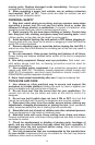
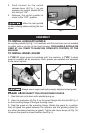
TO INSTALL AUXILIARY HANDLE
An auxiliary handle (H) Fig. 2 is furnished with this tool and can be installed
on either side or on top of the front housing. THIS HANDLE SHOULD BE
USED AT ALL TIMES TO MAINTAIN COMPLETE CONTROL OF THE
MACHINE.
ASSEMBLY
Fig. 2
H
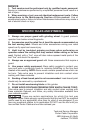
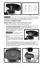
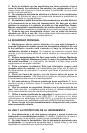
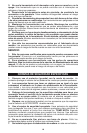
TO INSTALL WHEEL GUARD
A TYPE 27 wheel guard is furnished with the machine. A TYPE 1 wheel
guard is available as an accessory. Both guards are installed and adjusted
in the same manner.
A
B
Fig. 3
Always use an approved and properly adjusted wheel guard.
DISCONNECT TOOL FROM POWER SOURCE.
1. Rest the tool on its back with spindle facing up.
2. Align the protrusion (A) Fig. 3 on the guard flange with the slot (B) Fig. 3
on the mounting flange of the gear housing cover.
3. Seat the guard on the mounting flange. Rotate the guard to a position
that will place the guard between the operator and the grinding wheel (or
any other accessory requiring a guard). Tighten the clamp screw (A) Fig. 3A
to secure the guard in proper position (see Fig. 4).
B
➡
➡