


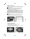
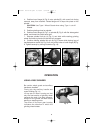
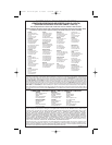
4. Position inner flange (A) Fig. 6 onto spindle (B), with round hub facing
outward, away from machine. Rotate flange until it drops into place on the
spindle.
CAUTION: Use Type 1 Wheel Guard when using Type 1 cut-off
Wheels.
5. Position grinding wheel on spindle.
6. Position outer flange (A) Fig.7 on spindle (B) Fig. 6 with flat side against
wheel, and thread into place hand tight.
7. Depress spindle lock pin (A) Fig. 8, and hold while rotating grinding
wheel clockwise by hand until spindle lock engages.
8. Continue holding spindle lock pin (A) Fig. 8 down while placing lugs of
handle/spanner wrench (A) Fig. 9 into two of the holes of outer flange (B) Fig.
9. Tighten securely by turning clockwise (Fig. 10).
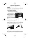
OPERATION
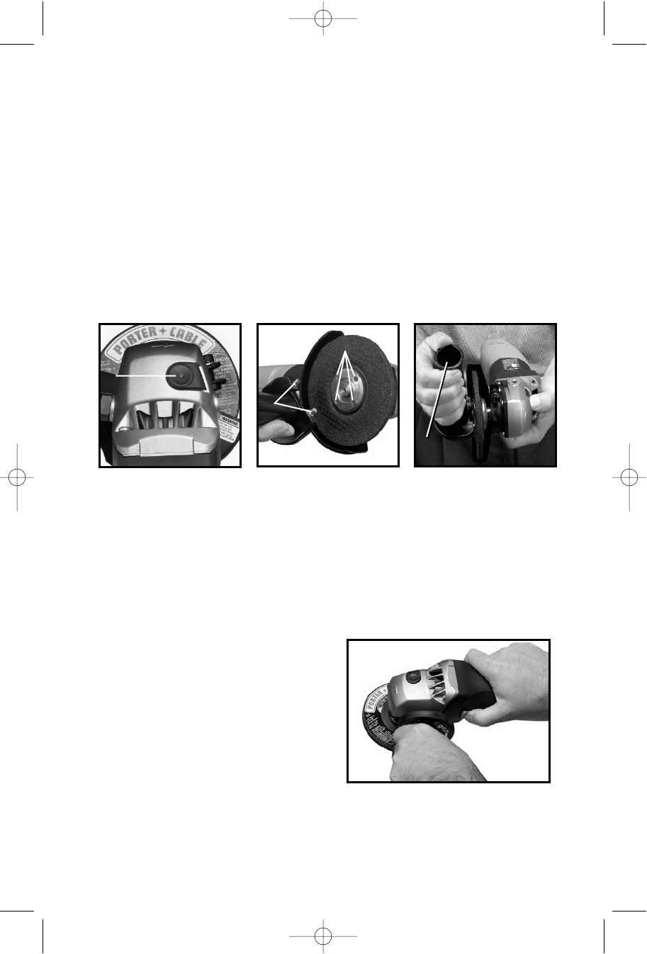
USING A DISC GRINDER
Be certain wheel guard and auxiliary
handle are installed.
Firmly grip the auxiliary handle and
motor housing (Fig. 11).
Lift up rear of motor housing so that
only the front section of grinding wheel
contacts the work. Use light pressure.
Always lift the grinder off work before
starting or stopping motor.
The arrow on the front gear housing
indicates the direction in which the
grinding wheel rotates.
9
Fig. 9
A
Fig. 8
A
Fig. 10
B
A
Fig. 11
300918- 08-13-02.qxd 9/13/02 3:26 PM Page 9