


11
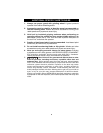
TO POSITION THE WHEEL GUARD
The Model 7425 and 7429 Grinders come with a TYPE 27 wheel guard
installed. To adjust:
Always use an approved and properly adjusted wheel guard.
DISCONNECT TOOL FROM POWER SOURCE.
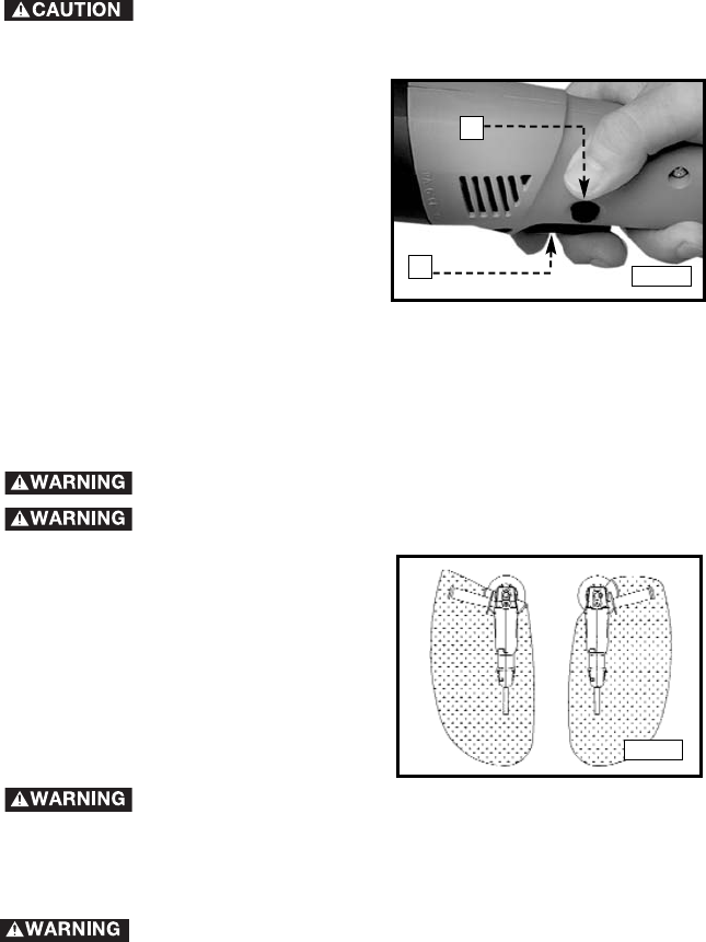
Turn the wheel guard in a clockwise
direction until it is in a position that
places the guard between the operator
and the grinding wheel (or other
accessory requiring a guard). (See Fig.
5).
Always make sure that the wheel guard is positioned between
the operator and the wheel, so that flying chips or pieces of a wheel that
might break will be deflected away from the operator.
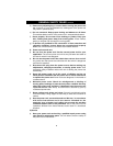
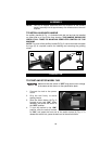
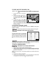
TO START AND STOP THE MODEL 7429
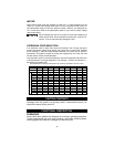
Make sure that the switch is "OFF" and power circuit
voltage is the same as that shown on the specification
plate.
1. Connect the tool to the power
source.
2. Squeeze the trigger switch (A) Fig.
4 to turn the tool “ON”. Release
the trigger switch to turn the tool
“OFF".
3. To lock the tool in the “ON”
position, squeeze the trigger
switch, push in the lock button (B)
Fig. 4, then release the trigger
switch. To remove the tool from the locked position, squeeze the trigger
switch and release.
Fig. 4
A
B
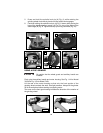
TO INSTALL GRINDING WHEEL
DISCONNECT TOOL FROM POWER SOURCE.
1. Rest the tool on its back with the spindle facing up.
2. Position the inner flange (A) Fig. 6 on the spindle (B), with the round hub
facing outward, away from the machine. Rotate the flange until it drops
into place on the spindle.
NOTE: If you use a Type 1 cut-off wheel, position the nut with the flat side to
the wheel.
3. Position the wheel on the spindle.
4. Position the outer flange (A) Fig. 7 on the spindle (B) Fig. 6 with the flat
side against the wheel, and thread into place hand tight.
Fig. 5