


ADJUSTING THE DEPTH OF CUT (1001 BASE)
To reduce the risk of injury, turn unit off and disconnect it from power source
before installing and removing accessories, before adjusting or when making repairs. An acci-
dental start-up can cause injury.
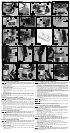
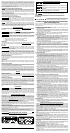
1. Open the clamp (A) Fig. 3.
2. Hold the base (E) and turn the power unit (F) Fig. 3 counter-clockwise until the tip of the bit is
above the bottom of the base.
3. Set the tool on a flat surface.
4. Turn the power unit (F) Fig. 3 clockwise until the bit touches the work.
5. Close the clamp (A) Fig. 3.
6. Rotate the depth adjusting ring (B) Fig. 3 until the zero-line is opposite the index line (D) on the
housing.
7. Open the clamp (A) Fig. 3.
8. Tip the router so that the bit is clear of the work surface. Turn the power unit (F) Fig. 3 clockwise
until the index line (D) on the motor housing reaches the desired depth indicated on the ring.
9. Close the clamp (A) Fig. 3.
NOTE: Setting the index line to 1/4" on the ring means the cutting edge of the bit is exposed 1/4"
below the base.
ADJUSTING THE SUB-BASE ALIGNMENT (ALL ROUTERS)
To reduce the risk of injury, turn unit off and disconnect it from power source
before installing and removing accessories, before adjusting or when making repairs. An acci-
dental start-up can cause injury.
Applications using a template guide require the bit to be centered in the guide. This, in turn, requires
the center hole in the sub-base to be in line with the collet of the motor unit. Your model has an
adjustable sub-base that has been aligned at the factory. The fixed-base router comes with the large
hole.
1. Loosen the sub-base mounting screws (C) Fig. 4 just enough to allow the sub-base (D) to
move.
2. Open the clamp (A) Fig. 4 (or screw (A) Fig. 17) and adjust the power unit so that the collet nut
(B) Fig. 4 engages the center hole in the sub-base (D). Allow the sub-base to center itself on the
collet nut. Close the clamp.
3. Tighten the sub-base mounting screws (C) Fig. 4 securely.
INSTALLING THE MOTOR (6931 PLUNGE BASE)
To reduce the risk of injury, turn unit off and disconnect it from power source
before installing and removing accessories, before adjusting or when making repairs. An acci-
dental start-up can cause injury.
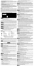
1. Support the motor clamp (D) Fig. 5 and loosen the motor clamp screw (A) Fig. 5 approximately
1/2" (13 mm) with the hex wrench (supplied).
2. Insert the motor unit into the base with the switch positioned at the front of the left handle. Align
the four pins (A) Fig. 7 (two of which are shown) in the motor case with the slots (B) Fig. 7 in the
base.
3. Seat the motor in the base and tighten the motor clamp screw.
REMOVING THE MOTOR (6931 PLUNGE BASE)
To reduce the risk of injury, turn unit off and disconnect it from power source
before installing and removing accessories, before adjusting or when making repairs. An acci-
dental start-up can cause injury.
1. Remove the clamp screw (A) Fig. 5, flat washer (B), lock washer (C), and clamp-locking nut (A)
Fig. 6.
2. Insert the hex wrench (A) Fig. 8 to contact the locking plate (B) Fig. 6. Tap lightly to release and
remove the locking plate.
3. Slide the motor out of the base.
4. Reattach the clamp screw, lock washer, flat washer, locking plate and clamp locking nut to the
base and tighten lightly.
ADJUSTING THE DEPTH OF CUT (6931 PLUNGE BASE)
To reduce the risk of injury, turn unit off and disconnect it from power source
before installing and removing accessories, before adjusting or when making repairs. An acci-
dental start-up can cause injury.
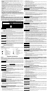
1. Loosen the depth rod locking knob (A) Fig. 9, and the depth indicator knob (D), allowing the
depth rod (E) to contact one of the turret stops (B). Normally the deepest desired cut is set with
the depth rod resting on the shortest turret stop (A) Fig. 10. The other two fixed stops (B) Fig. 10
provide reduced cutting depths of 1/4" (6.4 mm) and 1/2" (13 mm) respectively. You can adjust
the three stops (C) Fig. 10 to any desired height. You can utilize any combination of fixed and/
or adjustable stops to achieve the desired depths required for a particular job.
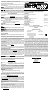
2. Release the plunge mechanism by pulling the locking lever (B) Fig. 11A to the left. Lower the
plunge mechanism until the router bit touches the work surface. Release the lever and push it
to the right to lock the mechanism in this position.
3. Tighten the depth-rod locking knob.
4. Position the depth indicator (C) Fig. 9 at the "0" position and tighten the knob.
5. Loosen depth-rod locking knob (A) Fig 9. Raise the indicator until it aligns with the graduation
representing the desired depth of plunge. (The example in Fig. 12 shows setting for 1" plunge.)
6. Turn the lower travel-limiting nut (A) Fig. 12 until it is approximately 1/4" above the top of the
the plunge housing. While holding the lower nut, turn the upper nut (B) until it "jams" against the
lower nut (A) Fig. 12.
Jam the travel-limiting nuts together to prevent movement (caused by vibration) which
could prevent full bit retraction.
Set the travel limiting nuts so that bit can be retracted into the base of the router, clear
of the workpiece.
DO NOT attempt to increase the plunge travel by readjusting the stop nut. Increasing
the travel beyond 2-1/2" (63.5 mm) can cause the mechanism to jam.
ADJUSTING THE PLUNGE LOCKING LEVER (6931 PLUNGE BASE)
To reduce the risk of injury, turn unit off and disconnect it from power source
before installing and removing accessories, before adjusting or when making repairs. An acci-
dental start-up can cause injury.
You can adjust the plunge-locking mechanism to reposition the lever (in the locked position), or to
compensate for wear.
1. While holding the lever in the upright position, remove the retaining screw (A) Fig. 13. Continue
to hold the lever through the remaining steps.
2. Use an 1/8" hex wrench (A) Fig. 14 (not furnished) to turn the adjustment screw counter-clock-
wise approximately 1/2 turn.
3. Move the lever to the desired locked position and tighten the adjustment screw.
4. Remove the hex wrench and replace the retaining screw.
ATTACHING THE POWER UNIT TO THE "D" HANDLE BASE (6911 BASE)
To reduce the risk of injury, turn unit off and disconnect it from power source
before installing and removing accessories, before adjusting or when making repairs. An acci-
dental start-up can cause injury.
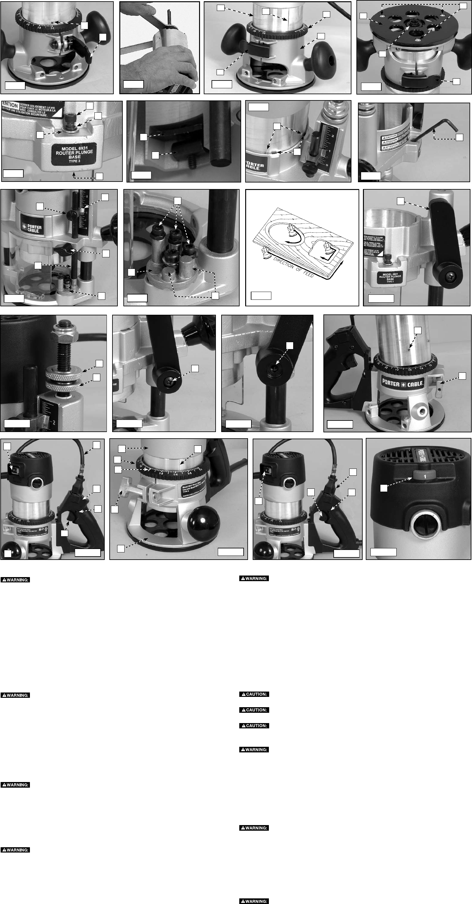
1. Loosen the clamp screw (A) Fig. 15 to set the power unit in the base unit.
2. Insert the motor unit into the base aligning the lower pin (B) with the groove in the base.
3. Rotate the motor unit into the base clockwise until the motor switch (A) Fig. 16 is directly above
the knob handle (B).
4. Connect the motor unit cord to the outlet in handle (C) Fig. 16.
5. Continue rotating the motor unit into the base until upper guide pins set rigidly into base.
6. Tighten the clamp screw firmly.
ADJUSTING THE DEPTH OF CUT (6911 BASE)
To reduce the risk of injury, turn unit off and disconnect it from power source
before installing and removing accessories, before adjusting or when making repairs. An acci-
dental start-up can cause injury.
Fig. 1
Fig. 2
A
B
Fig. 11
Fig. 3
B
D
F
E
Fig. 4
D
A
B
C
Fig. 5
A
B
C
D
Fig. 6
A
B
Fig. 7
A
B
Fig. 8
A
Fig. 9
A
D
C
E
B
Fig. 10
B
C
A
B
Fig. 11A
Fig. 12
B
A
Fig. 13
A
Fig. 14
A
Fig. 15
B
A
Fig. 16
B
A
F
E
C
F
B
C
D
A
E
Fig. 17
Fig. 18
Fig. 19
B
A
D
C
A
D
A