


12- ENG
D28299
Cooling System (not shown): This compressor contains an advanced design
cooling system. At the heart of this cooling system is an engineered fan. It is
perfectly normal for this fan to blow air through the vent holes in large
amounts. You know that the cooling system is working when air is being
expelled.
Air Compressor Pump (not shown: Compresses air into the air tank.
Working air is not available until the compressor has raised the air tank
pressure above that required at the air outlet.
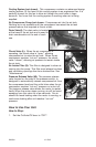
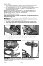
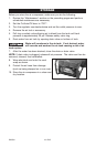
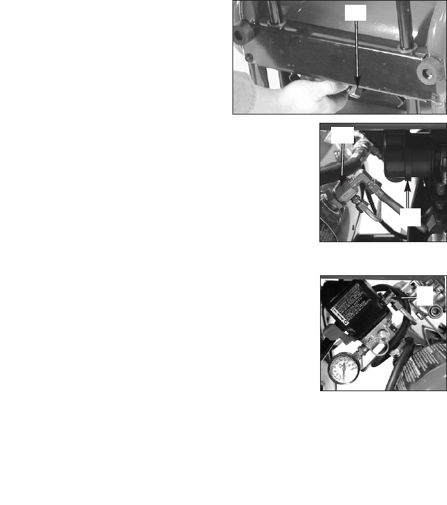
Drain Valve(I): The drain valve is located
at the base of the air tank and is used to
drain condensation at the end of each
use.
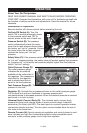
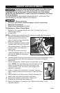
Check Valve (L): When the air compressor is
operating, the check valve is “open”, allowing
compressed air to enter the air tank. When the air
compressor reaches “cut-out” pressure, the check
valve “closes”, allowing air pressure to remain inside
the air tank.
Air Intake Filter (K): This filter is designed to clean air
coming into the pump. This filter must always be clean
and ventilation openings free from obstructions. See
"Maintenance".
Pressure Release Valve (M): The pressure release
valve located on the side of the pressure switch, is
designed to automatically release compressed air from
the compressor head and the outlet tube when the air
compressor reaches “cut-out” pressure or is shut off.
The pressure release valve allows the motor to restart
freely. When the motor stops running, air will be heard
escaping from this valve for a few seconds. No air
should be heard leaking when the motor is running, or
continuous leaking after unit reaches “cut-out”
pressure.
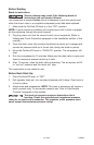
How to Use Your Unit
How to Stop:
1. Set the On/Auto/Off lever to “OFF”.
M
L
K
I