


8-ENG
INSTALLATION
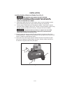
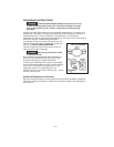
Installing Handles, Wheel, and Rubber Foot (Fig. 2)
THE WHEELS AND HANDLE DO NOT PROVIDE
ADEQUATE CLEARANCE, STABILITY OR SUPPORT FOR PULLING
THE UNIT UP AND DOWN STAIRS OR STEPS. THE UNIT MUST BE
LIFTED, OR PUSHED UP A RAMP.
1. Submerge handle grip (A) into warm soapy water to make installation easier.
Remove handle grip (A) from soapy water and slide onto handle (B).
2. Position legs of handle (B) inside compressor saddle. Align holes in handle
legs with holes in saddle. Using a 3/8” wrench to secure handle in place, using
the four screws provided (two screws (C), through each side of saddle).
It may be necessary to brace or support one end of the
unit when attaching the wheels and the rubber feet, because the air
compressor will have a tendency to tip.
3. Place shoulder bolt through wheel (D) and position it into the top hole of the
mounting bracket. Thread nut onto shoulder bolt and tighten firmly with a 9/16”
wrench. Repeat to install second wheel.
4. Clean and dry air tank leg (E) opposite wheels. Remove the protective paper
strip from the adhesive backed rubber foot strip. Position rubber foot strip to
the bottom of leg and press firmly into place.
Fig. 2
C
D
E
A
B