


8
USING THE TOOL
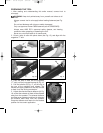
Complete all steps of PREPARING THE TOOL before using the tool.
To fire, grip tool firmly, position nose of tool onto work surface, push forward
on tool to depress safety, and squeeze trigger to fire a fastener. This “trigger
fire” method provides the most accurate fastener placement. This tool is
shipped from the factory with a “restrictive fire trigger” that only allows the tool
to be fired this way and is less likely to fire an unwanted fastener.
An alternate “bottom fire trigger” is available. The “bottom fire” trigger allows
the tool to be fired in two different ways.
1. The tool can be fired using the “trigger fire” method described above.
OR
2. Grip tool firmly, depress and hold trigger while pushing the tool firmly
against work surface. The tool will fire a fastener each time the safety is
depressed. This method is known as “bottom fire” and allows very fast
repetitive fastener placement.
The “bottom fire trigger” is available free-of-charge by calling 1-800-321-9443
in the United States and Canada or 001-731-660-9374 outside the United
States and Canada, and providing tool model and serial number. For
identification purposes: the Bottom Fire Trigger is black and the Restrictive Fire
Trigger is red.
WARNING: Remove finger from trigger when not driving fasteners.
Never carry tool with finger on trigger: tool will fire a fastener if safety
is bumped.
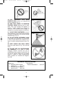
WARNING: Keep tool pointed in a safe direction at all times.
WARNING: Never attempt to drive a fastener into material that is too
hard, or at too steep an angle, or near the edge of the workpiece. The
fastener can ricochet causing personal injury.
WARNING: Disconnect tool from air supply before performing
maintenance, clearing a jammed fastener, leaving work area, moving
tool to another location, or handing the tool to another person.
WARNING: Clean and inspect tool daily. Carefully check for proper
operation of trigger and safety mechanism. Do Not use the tool unless
both the trigger and the safety mechanism are functional, or if the tool
is leaking air or needs any other repair.
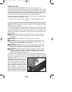
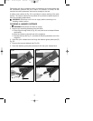
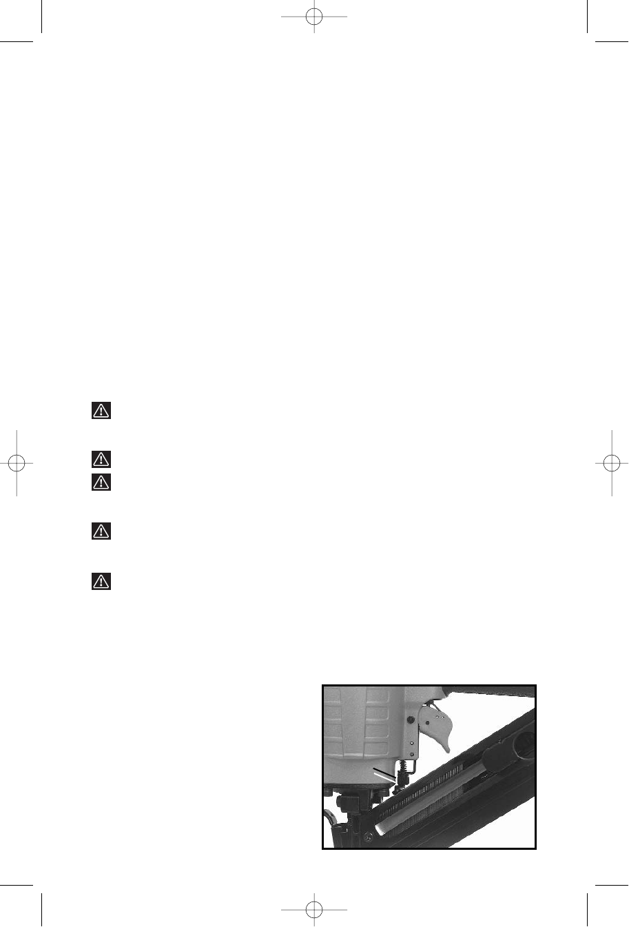
The depth to which a fastener is driven is controlled by the depth adjustment
knob (A) Fig. 19. The depth of drive is factory adjusted to a nominal setting.
Test fire a fastener and check depth. If a change is desired, rotate the
adjustment knob (A) Fig. 19: the
adjustment knob has detents every
1
/4
turn. Rotate the knob clockwise (see
Fig. 19), to increase the depth of
drive, rotate the knob counterclock-
wise to decrease the depth of drive.
Test fire another fastener and check
depth. Repeat as necessary to
achieve desired results. The amount
of air pressure required will vary
depending on the size of the fastener
and the material being fastened.
Fig. 19
A
903090 - 06-30-01.qxd 9/25/02 1:53 PM Page 8