


Make sure the wheel has come to a complete stop before laying the tool down.
Allow the tool to reach full speed before touching tool to the work
surface. Lift the tool from the work surface before turning the tool off.
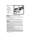
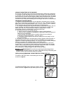
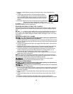
SPINDLE LOCK
The spindle lock button (3) is provided to prevent the spindle
from rotating when installing or removing wheels. Operate
the spindle lock only when the tool is turned off, the battery
is removed, and the wheel has come to a complete stop.
Do not engage the spindle lock while the
tool is operating. Damage to the tool will result and
attached accessory may spin off possibly resulting in injury.
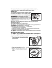
To engage the lock, depress the spindle lock button shown
in figure J and rotate the spindle until you are unable to
rotate the spindle further.
Mounting and Using Depressed Center Grinding Wheels and
Sanding Flap Discs
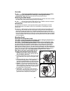
MOUNTING AND REMOVING HUBBED WHEELS
Turn off tool and remove battery before making any adjustments or
removing or installing attachments or accessories.
Hubbed wheels install directly on the 5/8 in.-11 threaded spindle.
1. Thread the wheel on the spindle by hand.
2. Depress the spindle lock button and use a wrench to tighten the hub of the wheel.
3. Reverse the above procedure to remove the wheel.
Failure to properly seat the wheel before turning the tool on may result in
damage to the tool or the wheel.
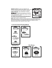
MOUNTING NON-HUBBED WHEELS
Turn off tool and remove battery before making any adjustments or
removing or installing attachments or accessories.
Depressed center Type 27 grinding wheels must be used with included flanges. See
pages 13 and 14 of this manual for more information.
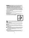
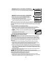
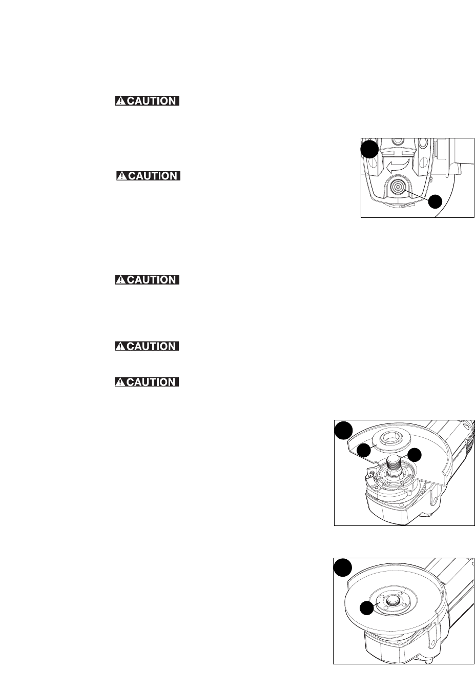
1. Figure K - Install the unthreaded backing flange
(7) on spindle (4) with the raised section (pilot)
against the wheel.
2. Place wheel against the backing flange, centering the wheel on the raised section
(pilot) of the backing flange.
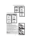
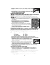
3. Figure L - While depressing the spindle lock
button, thread the threaded clamp nut (8) on
spindle.
15
:
:
:
:
:
3
J
K
L
7
4
8