


11
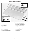
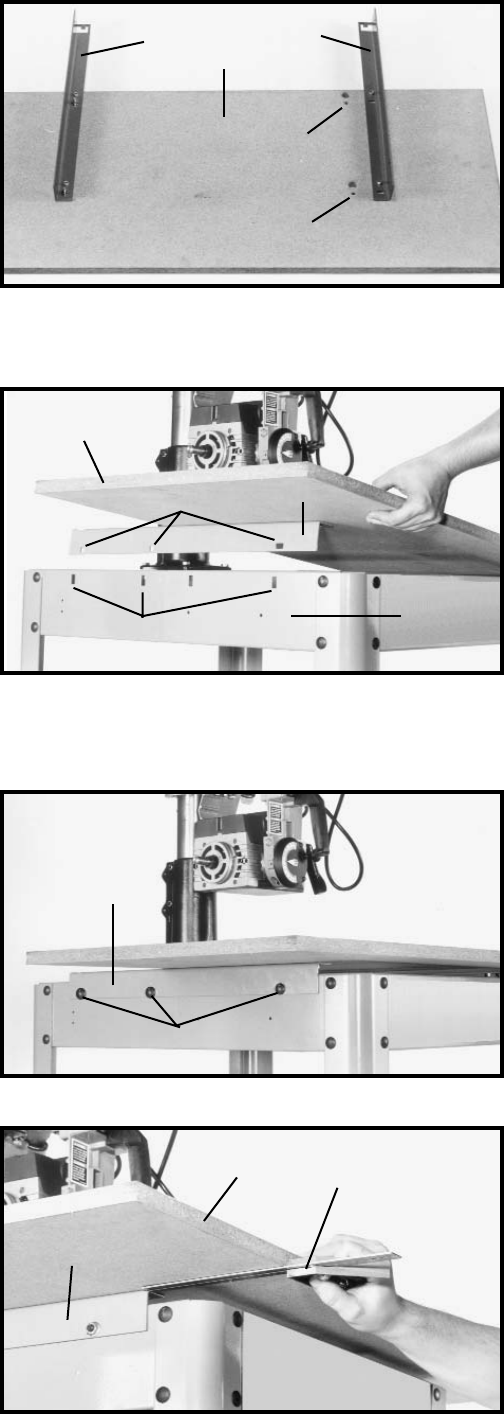
TABLE SUPPORTS
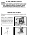
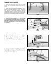
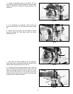
1. Place front table board (A) Fig. 16, on a stable
surface with counter-bored holes facing down, as
shown.
2. Fasten left and right table supports (B) Fig. 16, to
bottom of front table board (A) as shown, by inserting
four 1/4-20x1" round head screws up through
counterbored holes (D), in table board (A) and table
supports (B). Secure in place using four 1/4-20 flanged
hex nuts. Do not completely tighten nuts at this time.
Fig. 16
A
B
B
D
D
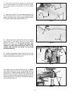
3. Place front table board (A) Fig. 17, onto saw base
(G), so that table supports (B) straddle the outside of
saw base (G) and three holes (H) in each table support
(B) line up with three slots (J) in each side of saw base
(G) as shown.
Fig. 17
A
B
H
J
G
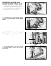
4. Secure table supports, one of which is shown at
(B) Fig. 18, to each side of saw base using six 5/16-
18x5/8" carriage head screws (L) and six 5/16-18
flanged hex nuts. Do not completely tighten nuts at this
time. IMPORTANT: Insert screws through table
supports and saw base from the outside.
Fig. 18
B
L
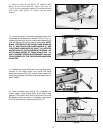
Fig. 20
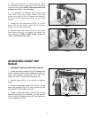
5. Using a combination square (M) Fig 20, check the
left and right front edge of table board (A) to make
certain both sides are the same distance from the edge
of each table support (B) Fig. 20.
M
A
B