


2
Reciprocating Air Compressor Pumps
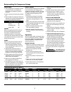
VENTILATION
1. If the compressor is located in a total-
ly enclosed room, an exhaust fan
with access to outside air must be
installed.
2. Never restrict the cooling fan exhaust
air.
3. Never locate the compressor where hot
exhaust air from other heat generating
units may be pulled into the unit.
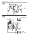
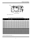
WIRING
Refer to the general product manual.
All electrical hook-ups must be per-
formed by a qualified electrician.
Installations must be in accordance
with local and national electrical codes.
Use solderless terminals to connect the
electric power source.
PIPING
Refer to the general product manual.
1. Make sure the piping is lined up
without being strained or twisted
when assembling the piping for the
scroll compressor.
2. Appropriate expansion loops or
bends should be installed at the com-
pressor to avoid stresses caused by
changes in hot and cold conditions.
3. Piping supports should be anchored
separately from the compressor to
reduce noise and vibration.
4. Never use any piping smaller than
the compressor connection.
5. Use flexible hose to connect the out-
let of the compressor to the piping so
that the vibration of the compressor
does not transfer to the piping.
SAFETY VALVES
Tank mounted compressors are shipped
from the factory with safety valves
installed in the tank manifold. The flow
capacity of the safety valve is equal to
or greater than the capacity of the
compressor.
1. The pressure setting of the safety
valve must be no higher than the
maximum working pressure of the
tank.
2. Safety valves should be placed ahead
of any possible blockage point in the
system, i.e. shutoff valve.
3. Avoid connecting the safety valve
with any tubing or piping.
4. Manually operate the safety valve
every six months to avoid sticking or
freezing.
Operation
Powerex single stage compressors oper-
ate at a maximum pressure of 140 PSIG.
Compressor RPM’s are established by
Powerex based on horsepower and
operating pressure.
BEFORE START UP
1. Make sure all safety warnings, labels
and instructions have been read and
understood before continuing.
2. Remove any shipping materials,
brackets, etc.
3. Confirm that the electric power
source and ground have been firmly
connected.
4. Be sure all pressure connections are
tight.
5. Check to be certain all safety relief
valves, etc., are correctly installed.
6. Check that all fuses, circuit breakers,
etc., are the proper size.
7. Make sure the inlet filter is properly
installed.
8. Confirm that the drain valve is closed.
9. Visually check the rotation of the
compressor pump. If the rotation is
incorrect, have a qualified electrician
correct the motor wiring.
START-UP AND OPERATION
1. Follow all the procedures under
“Before start-up” before attempting
operation of the compressor.
2. Switch the electric source breaker on.
3. Open the tank discharge valve com-
pletely.
4. Check that the compressor operates
without excessive vibration, unusual
noises or leaks.
5. Close the discharge valve completely.
6. Check the discharge pressure. Also
make sure the air pressure rises to the
designated pressure setting by check-
ing the discharge pressure gauge.
7. Check the operation of the pressure
switch or the pilot valve for continu-
ous run units by opening the stop
valve and confirming the compressor
starts or reloads as pressure drops.
Switch the breaker OFF if the compres-
sor is not to be used for a long period
of time.
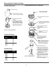
Two stage units are
equipped with head
unloaders for continuous operation.
NOTICE
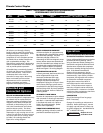
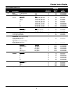
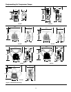
Max SCFM @ RPM @ Number/ Flywheel Weight
Model HP psig 100 psig 100 PSIG Cylinders Bore Stroke Outer Diam. Drive (lbs.)
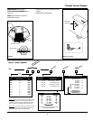
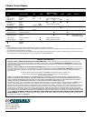
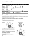
Dimensions (Refer to Figure 2)
Minimum Clearances
Above 24”
Drive belt side 12”
Other sides 20”
CS100P .75/.5 140 2.3/1.7 990/805 1 1.9 2.2 11.2 1GR-A 28
LPS010 1.5/1 140 5.1/3.4 900/665 1 2.6 2.6 10.5 1GR-A 34
LPS020 2 140 7.7 720 2 2.6 2.4 13.7 1GR-B 65
LPS030 5/3 140 15.4/11.5 1050/765 2 3.0 2.9 14.6 1GR-B 76
LPS075 7.5 140 29.2 790 2 4.1 3.35 18.3 2GR-B 116
LPS100 15/10 140 62.1/41.3 1080/695 3 4.1 3.35 19.7 2GR-B 137