


5
Scroll Air Compressors
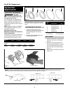
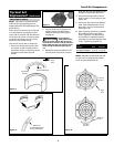
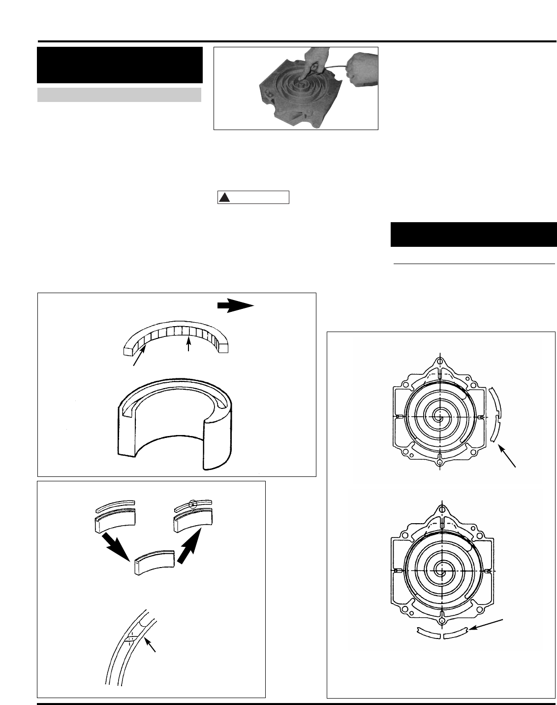
Figure 9
Lip Direction
Lip Surface
(Inside)
Enter
Side
Lip Side
(Grooved Bottom)
Machined
To Avoid Movement
During Installation
Figure 10
Dust
Seal
3 o’clock
Position
6 o’clock
Position
Back-up
Tube
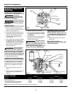
Figure 8
Figure 11
NOTE: Tips seals for Fixed Scroll and
Orbit Scroll have opposing seal cut
angels (See NOTE and explanatory dia-
gram below).
Insert tip seal so that the lip of tip seal
is on the bottom of seal groove and
inner side of involute and the direction
of lip faces the center of involute (curv-
ing spiral). See Figure 9. This is to be
done for both FS and OS sets.
Use caution not to tear or distort lip.
1. Insert new HP tip seal from the cen-
ter section for OS or Orbit Scroll so
that there will be no clearance at the
tip (start) section (See Figure 8
and 9).
2. Insert so that new LP tip seal will
contact closely with HP tip seal
inside Scroll Groove (See Figure 7
on page 4).
Insert approxi-
mately half of the
LP tip seal and remove the tip seal to
confirm that a notch in the tip seal has
been achieved. This will prevent move-
ment during installation (See Figure
11).
3. Repeat the same procedure for FS
or Fixed Scroll tip seal set, remove
!
CAUTION
INSERTING TIP SEALS
Tip Seal Set
Replacement
(Continued)
both the dust seal and backup tube
located on outermost side FS set.
4. Insert new backup tube in the FS
Scroll in the 6 o’ clock position (See
Figure 10).
5. Insert new dust seal on the backup
tube. Face seamed section of the
dust seal in the 3 o’clock position
(See Figure 10).
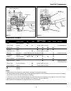
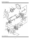
8. After replacing tip seal set, reassem-
ble Fixed Scroll set to the Orbit
Scroll. Tighten 6 nuts temporarily
and confirm if crankshaft rotates
smoothly by hand and tighten them
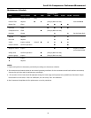
firmly. Tightening torques are:
NOTE: Assemble so that dust seal and
tip seal will not drop between Orbit
Scroll set and Fixed Scroll set.
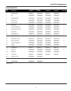
Bolt
Torque First Second
SLAE03/SLAE03HP 15 in lb. 175 in lb.
SLAE05/SLAE05HP 15 in lb. 175 in lb.