


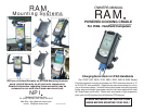

CONTENTS, DESCRIPTION & ASSEMBLY INSTRUCTIONS
Before proceeding with assembly of powered docking cradle, check the contents of
package to make certain all parts are included. If any parts are missing, please
contact NPI for a replacement part at: support@ram-mount.com
A
B
C
D
E
F
G
H
J
K
L
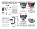
A. 1 qty. RAM Main Plastic Housing
B. 1 qty. RAM PCB Plastic Cover
C. 2 qty. #8 X 1 1/4” Long Screws
D. 1 qty. 10’ Long Power Cord
E. 1 qty. 10’ Long Coiled Power
Cord With Cigarette Plug
F. 1 qty. Power Printed Circuit
Board
G. 1 qty. Input / Output Printed
Circuit Board
H. 1 qty. IPAQ Male Connector
Printed Circuit Board
J. 2 qty. of ea. #8-32 X 5/8” & 1/2”
Long Screws & #8 Nuts
K. 1 qty. Non-Null Modem Wire
Harness (BLACK)
L. 1 qty. Null Modem Wire Harness
(RED)
STEP 2
STEP 3
STEP 4
STEP 5
STEP 1
First determine what type of connection
you require for the serial port. We offer 2
different wire harnesses, a non-null-
modem (K Black) and null modem (L
Red). To determine what type you
require, contact the manufacturer of
your electronic device that you are
attaching to the powered docking
cradle. Once determined, select the
appropriate colored wire harness and
attach it to the corresponding PCB’s G &
H as shown in the STEP 1 photo. Note,
the ends have different numbers of
connectors so they can’t be reversed.
Attach the 10 qty. connector socket to
the G PCB & the 11 qty. connector
housing to the H PCB. Connect the 3
wire socket on the G PCB to the pins on
the F PCB. Make certain that the label
marked “TOP FACING” is toward you
as shown in the STEP 1 photo.
Assemble power PCB (F) on the three
corresponding pins on the housing (A)
as shown in STEP 2 photo.
Assemble Input / Output PCB (G) to the
two slotted posts on housing (A) as
shown in STEP 3 photo. Note: pre-
bend the wire harness to aid in holding
the PCB’s in place and note the
direction path of the wires.
Using a pointer, or similar device, insert
it through the serial port hole in plastic
cover (B) to aid in holding the PCB’s in
place while aligning and attaching the
cover with the 2 screws (C). Gently
snug the screws until the cover (B)
touches housing (A).
The iPAQ Male PCB (H) has 2 different
sized connectors. Before assembly, try
the connector into your device to
determine which one is to be used.
Once that is determined, look on
housing (A) to see the Small & Large
lettering to indicate the side that the
PCB will be on. Then assemble it as
shown in STEP 4 photo. Note: pre-
bend the wire harness to aid in holding
the PCB’s in place and note the
direction path of the wires.
F
G
H
K
L
11 qty. Connector
10 qty. Connector
Black
non-null
modem
Power
PCB
IPAQ Male Connector PCB
Input / Output
PCB
Red
null modem
Locating
Pins
Large Side
Small Side
Wire Path
No Wires
This Area
Slotted Posts