


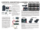

CONTENTS, DESCRIPTION & ASSEMBLY INSTRUCTIONS
Before proceeding with assembly of powered docking cradle, check the contents of
package to make certain all parts are included. If any parts are missing, please
contact NPI for a replacement part at: support@ram-mount.com
A
B
C
D
E
F
G
H
J
K
L
M
A. 1 qty. RAM Main Plastic Housing
B. 1 qty. RAM PCB Plastic Cover
C. 1 qty. Input / Output Printed Circuit
Board
D. 1 qty. Power Printed Circuit Board
E. 1 qty. IPAQ Male Connector Printed
Circuit Board
F. 1 qty. each Null Modem Wire
Harness (RED), Non-Null Modem Wire
Harness (BLACK),
G. 4 qt. Side Adjusting Retaining Arms
H. 4 qty. each #6-32 X 3/8” Machine
Screws and Nylock Nuts
J. 1 qty. #4 X 1/4” Screw
K. 2 qty. each #4-40 x 3/4” Hex Head
Machine Screw & Nylock Nut
L. 4 qty. #6 X 3/4” Sheet Metal Screw
M. 2 qty. each Spacers: White 1/4”,
Green 3/16”, Black 1/8”, Blue 1/16”,
Red 1/32”
STEP 3 STEP 4 & 5
STEP 1
First determine what type of connection
you require for the serial port. We offer
2 different wire harnesses, a non-null-
modem (Black) and null modem (Red).
To determine what type you require,
contact the manufacturer of your
electronic device that you are attaching
to the powered docking cradle. Once
determined, select the appropriate
colored wire harness and attach it to
the corresponding PCB’s G & H as
shown in the STEP 1 photo. Note, the
ends have different numbers of
connectors so they can’t be reversed.
Attach the 10 qty. connector socket to
the G PCB & the 11 qty. connector
housing to the H PCB. Connect the 3
wire socket on the G PCB to the pins on
the F PCB. Make certain that the label
marked “TOP FACING” is toward you
as shown in the STEP 1 photo.
Step 3 Install C PCB & D PCB into B cover and secure D PCB with J screw.
Make certain that the 3 pins in B cover align with the 3 holes in D PCB. cover with
the 2 screws (C).
Step 4 With iPAQ device still installed in A housing attach B cover with A housing
using L screws. Note; make certain screws are properly aligned and DON’T
OVER TIGHTEN.
Step 5 Attach G side arms with H screws and nuts. With iPAQ device installed in
A housing, G adjust arms and GENTLY tighten screws. Note, insert 4 qty.
business cards between the side arms and the iPAQ device to provide the proper
clearance for easy use.
Your RAM Powered Docking Cradle is now ready for use.
F
E
D
C
11 qty.
Pin
Connector
10 qty.
Pin
Connector
Power PCB
IPAQ Male Connector PCB
Input / Output PCB
Step 2 Before the proceeding look at the pictures in Step 2 and specifically how the
E PCB is attached to A housing. Check the E PCB Application Chart to see what M
washers are required for your iPAQ model. Install the K screws in E PCB along with
the nuts & appropriate colored washers M to properly space the E PCB to align with
the iPAQ device. Make certain to have the K screws, nuts & correct M washers on
the correct side of the PCB. The K nut must have a M washer under it or the PCB
may be damaged. IMPORTANT: DON’T OVER TIGHTEN ANY NUTS, OR
SCREWS IN THE REMAINING STEPS. Insert the iPAQ device into the cradle and
carefully align the E PCB into the mating connector. The 2 qty K hex head screws
will slide into the A housing. Make certain the E PCB is fully engaged into the iPAQ
device and then gently tighten the K nylock nuts.
STEP 2
Model
Serial
Pass
Through
Power
PCB Washer
Washer For
Nut
h1900
NO
NO
NO
NA
NA
h2200
YES
YES
YES
WHITE, BLACK
BLUE, RED
hx2415
YES
YES
YES
WHITE, BLUE,
RED
GREEN
rx3115
YES
NO
YES
WHITE, BLUE
GREEN
3650
NO
NO
NO
NA
NA
3955
YES
DATA YES,
POWER NO
YES
RED
WHITE,
GREEN, BLUE
h4100
YES
YES
YES
WHITE, BLACK,
RED
BLUE
h4300
YES
YES
YES
GREEN, RED
WHITE, BLUE
hx4700
YES
YES
YES
GREEN
WHITE, BLUE
h5555
YES
YES
YES
RED
WHITE,
GREEN, BLUE
h6315
NO
YES
YES
WHITE
GREEN