


LABC1 • 13
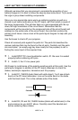
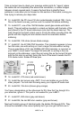
5. Install C1, 1000 µF electrolytic capacitor. This part also must be
installed properly to function. In fact, this capacitor has the potential to
explode if installed in reverse polarity. The PC board silkscreen shows the
positive hole and the band on the capacitor shows the negative side.
You’ll also note that the lead closest to the stripe is shorter than the other
lead; this also indicates the negative side. Save the long leads you clip off
from this part. They’re great for the jumpers you’ll need to install later.
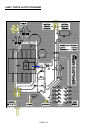
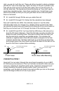
Next we’ll install VR1. You’ll need to locate the following parts: the LM317,
HS1 is the black finned heatsink, the #4-40 3/8” screw, and the #4-40 kep nut.
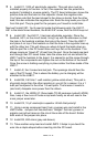
6. Install VR1, the LM317, 3 terminal adjustable regulator. Place the
heatsink, HS1, on the circuit board, lining it up with the silkscreen so that
the hole in the heatsink matches the hole in the board. Take the LM317
and place it on top of the heatsink so that the hole in the regulator lines up
with the other two. This will show you where to bend the leads down so
that the part fits in the PC board holes and lays flat on the heatsink. This
allows maximum “bleed off” of heat from the part. Once the leads are bent
and through their PC board holes, take the screw and nut and attach the
LM317 and the heatsink to the board. It is easiest to put the screw through
the top of the components and tighten the nut on the bottom of the board.
Once the screw is holding everything in place solder the three leads of the
LM317.
7. Install J2, the 2 screw terminal jack. The openings should face the
rear of the PC board. This is where the battery you’re charging will be
attached to the LABC1.
8. Install R6, 0.47ohm 1 watt resistor (yellow-violet-silver). This part is
physically larger than the other resistors in your kit for a reason; it is a 1
watt part compared to the other 1/4 watt parts. That means it needs to
(and can!) dissipate more power than the others.
9. Install U1, the LM334 IC (three leads TO-92 package marked LM334).
Also, keep a few more of those scrap leads handy as we will need a few
more jumper wires later.
10. Install C2, 10 µF electrolytic capacitor. Watch that polarity!
11. Using a scrap component lead, form a jumper wire and install in the
JMP3 holes. Jumpers act like electronic “bridges” that carry power or
signals over active traces on the circuit trace side of the board. Solder
both ends of the jumper into place.
12. Install R3, 820 ohms (gray-red-brown).
13. Take another scrap lead and install JMP2. It helps to pre-bend the
wire into a staple shape before inserting into the PC board.