


3
used in accordance with the instructions, may cause harmful interference to radio
communications. However, there is no guarantee that interference will not occur in a
particular installation. If this equipment does cause harmful interference to radio or
television reception, which can be determined by turning the equipment off and on, the
user is encouraged to try to correct the interference by one or more of the following
measures:
• Reorient or relocate the receiving antenna.
• Increase the separation between the equipment and receiver.
• Connect the equipment into an outlet on a circuit different from that to which the
receiver is connected.
• Consult the dealer or an experienced radio/TV technician for help.
• Fixture must be connected to a 120 Volt, 60 Hz power source. Any other connection
voids the warranty.
• This motion activated twin floodlight should be installed by persons with experience in
household wiring or by a qualified electrician. The electrical system, and the method
of electrically connecting this fixture to it, must be in accordance with the National
Electrical Code and local building codes.
• For proper operation and protection against damage, the motion sensor head control
switches must be facing the ground.
• Disassembly of your fixture will void the warranty.
SAVE THESE INSTRUCTIONS.
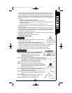
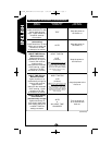
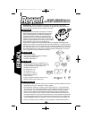
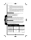
WhWhator best results
• Install your fixture 8-12 feet above ground. The motion sensor
is less sensitive above 12 feet.
• Locate fixture so motion moves across detection zone (L).
• Locate fixture away from heat producing sources to prevent fa l s e
t ri g g e ri n g . Also be careful not to include objects such as heat pumps, air conditioners,
l a u n d ry ve n t s, white walls and water in the detection zone whenever possibl e.
• Locate fixture away from moving objects such as trees and street traffic.
• DO NOT install more than one motion activated floodlight on one wall switch.
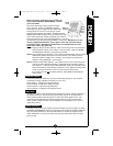
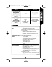
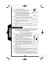
Step 1:Turn off the power at the main fuse/breaker box.
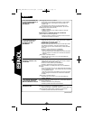
Step 2: Install protective lamp covers onto lampholders by
lining up the nipples on the covers, over the
lampholder slots. Lock into place by twisting
covers counterclockwise (M).
Step 3: Line up the holes on the mounting bracket with the holes on
your junction box. Using either (2) #6 screws or (2) #8 screws
(depending on size of the holes in your junction box), attach
the mounting bracket to your junction box (N).
Step 4: Thread fixture wires through coverplate gasket.
Step 5: Connect fixture black wire to house black wire, fixture
white wire to house white wire, and copper colored ground
wire (coming from the fixture coverplate) to house ground
wire using wire nuts provided.
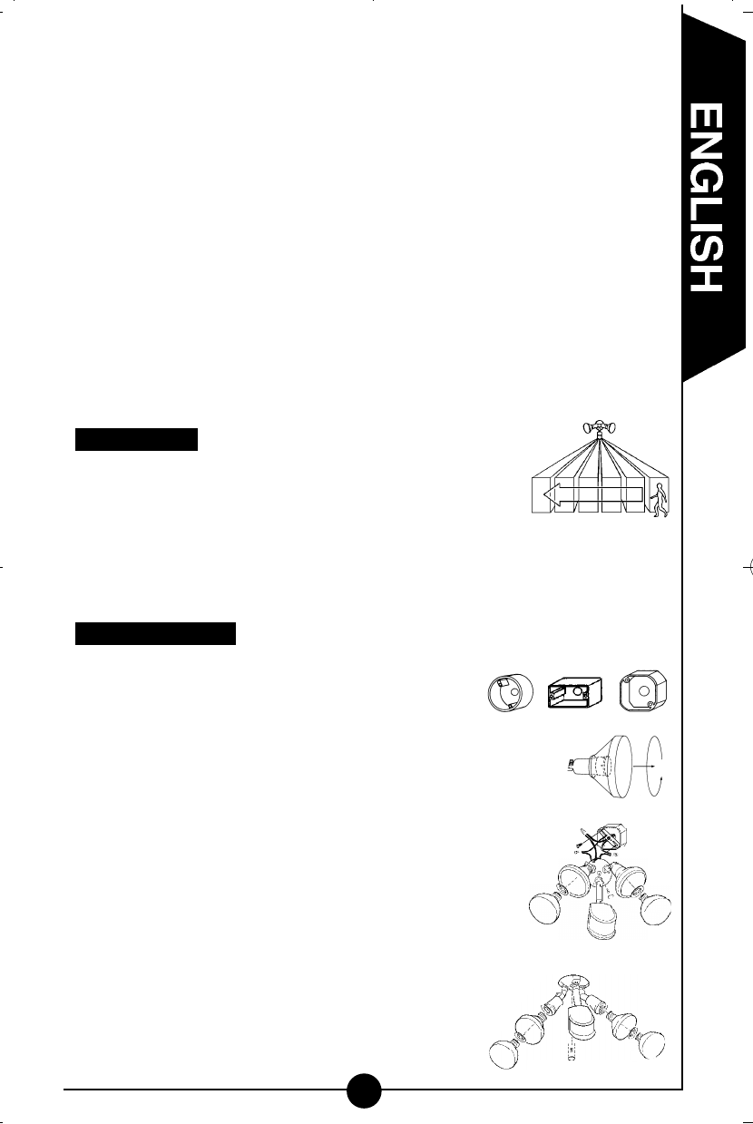
Step 6: Attach fixture to the mounting bracket using the center bolt
provided. Insert plastic color matched plug in center
bolt hole for finished appearance.
Step 7: Apply silicone caulking around edges of coverplate and in
any open holes to provide a watertight seal from rain and
moisture.
Step 8: Insert gaskets into lampholders and screw bulbs into
each lampholder (do not overtighten bulbs).
Step 9: Turn power on at main fuse/breaker box.
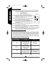
Mounting your fixture
For best results
L
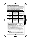
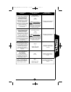
Round Rectangular (horizontal) Octagonal
Your fixture mounts
to the following standard
junction boxes:
N
(wall mount)
M
(eave mount)
MS249R_MS249RW 325-1486.qxd 6/20/06 4:02 PM Page 3