


16
MAINTENANCE
WARNING:
When servicing use only identical RIDGID® replace-
ment parts. Use of any other parts may create a
hazard or cause product damage.
WARNING:
The random orbit sander should never be connected
to a power supply when you are assembling parts,
making adjustments, cleaning, performing mainte-
nance, or when the tool is not in use. Disconnecting
the tool will prevent accidental starting that could
cause serious injury.
General
Avoid using solvents when cleaning plastic parts. Most
plastics are susceptible to damage from various types of
commercial solvents and may be damaged by their use.
Use clean cloths to remove dirt, carbon dust, etc.
WARNING:
Do not at any time let brake fluids, gasoline, petro-
leum-based products, penetrating oils, etc. come in
contact with plastic parts. They contain chemicals
that can damage, weaken, or destroy plastic.
Electric tools used on fiberglass material, wallboard,
spackling compounds, or plaster are subject to accelerated
wear and possible premature failure because the fiber-
glass chips and grindings are highly abrasive to bearings,
brushes, commutators, etc. Consequently, we do not
recommended using this tool for extended work on these
types of materials. However, if you do work with any of
these materials, it is extremely important to clean the tool
using compressed air.
WARNING:
Always wear safety goggles or safety glasses with
side shields during power tool operation or when
blowing dust. If operation is dusty, also wear a dust
mask.
Bearing Lubrication
All of the bearings in this tool are lubricated with a suffi-
cient amount of high grade lubricant for the life of the tool
under normal operating conditions. Therefore, no further
lubrication is required.
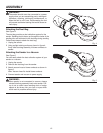
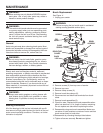
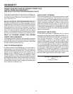
Brush Replacement
See Figure 11.
1. Unplug your sander.
WARNING:
Failure to unplug the tool could result in accidental
starting causing possible serious injury.
2. Remove screws (3) from top cover of sander.
3. Remove top cover.
4. Remove clamp screws (2).
5. Remove brush tube clamps (2).
6. Disconnect red and black lead terminals from brush
tubes.
7. Remove brush assemblies (2).
8. Check for wear. Replace both brush assemblies when
either has less than 1/4 in. length of carbon remaining.
Do not replace one side without replacing the other.
9. Reassemble using new brush assemblies. Make sure
curvature of brush matches curvature of motor and that
brush moves freely in brush tube.
10.Reassemble by reversing the steps listed above.
11.Tighten all screws securely. Do not over tighten.
Fig. 11
SCREWS
TOP
COVER
BRUSH
ASSEMBLY
CLAMP
SCREWS
BRUSH TUBE
CLAMPS
BLACK
LEAD
RED
LEAD
BRUSH
ASSEMBLY